This thread has been locked.

If you have a related question, please click the "Ask a related question" button in the top right corner. The newly created question will be automatically linked to this question.

LDC1614: Network between coils and LDC1614

Genius 9880 points
Part Number: LDC1614
Other Parts Discussed in Thread: TIDA-01102, TS5A23160

Hi,

Customer is asking the best solution for their application, please see details below.

"

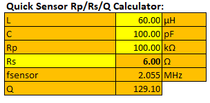
In the development of a sensor solution based on the LDC1614, I have successfully done tests with a micro controller, LDC1614 (via I2C), a network based on small signal relays, and capacitors and coils sensing the target. I use 8 coils together with one LDC1614.

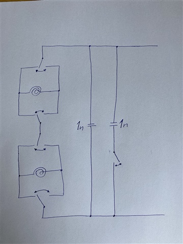
The micro controller sets the relays in different states, which means that coils are sometimes coupled two-and-two in series and sometimes alone. Capacitors are also added/removed by relays, so that my target frequency is reached both when coils are in series and stand alone.  Once the relays as set and the signal is stable, the frequency is read by the micro controller.

The solution is successful if we look at is as a feasibility study, coils together with LDC1614 gives a useful result. In order to reach a final solution, the relays will need to be replaced by a faster solution and a solution that will not wear out when switched a lot.

A cannot just add more LDC1614 circuits as I need to use the same coils in both a series solution and in a stand alone solution.

With your knowledge around the LDC1614 in mind, which solutions do you see instead of relays?
Mosfet?
Optocoupler?
Something else?

"

Thank you in advance.

Regards,
Maynard

  • Hello Maynard, 

    We have the TIDA-01102 reference design that uses analog MUXs to switch between channels. The key to having something like this in between the coil and the IC is to make sure the part has the bandwidth to support the sensor frequency. If it does not have enough bandwidth, the sensor oscillation may fail and you won't get a clean reading from the device. It seems like your application may need an analog switch instead of a MUX but the same principle applies. 

    Best Regards, 

    Justin Beigel

  • Hi Justin,

    Customer have followup questions, please see details below.

    "I have looked at TIDA-01102 and see that you use an analog switch to choose which coil-capacitor-pair to connect to the capacitive sensor circuit.

    My solution contains some differences compared to your solution. One is that I need to put the switch between the coil and capacitor. I fear that the added resistance in the switches will influence the signals too much. I also need to put some (in attached solution 4 or 5) switches in the LC-circuit.The analog switch that you use in your example has an internal resistance of about 11 Ohms. Will a solution where I add 5*11 Ohms in series with the capacitor and coil work?

    I also have a question regarding the analog switch. It seams as the switch can work with analog currents in both directions, but only at positive voltages. Is positive voltages enough?

    The attached circuit diagram looks similar to what I work with today, where relays are part of the solution, gives a frequency at 700kHz.

     "

    Regards,
    Maynard

  • Hello Maynard, 

    The added resistance can change the LDC response but if you take it into consideration in your coil design you can still get it to work. I assume the relays you used also added some resistance to the circuit so you may be able to find a switch that matched their internal resistance. Something like the TS5A23160 may work since it proves a low resistance option. Since your resistance will be known, you can use it to make sure the overall Rp is still within device spec and that the resulting change to the Q factor won't become a problem. If you need, the Inductive Sensing Design Calculator Tool (Rev. G) has some quick calculations that you can use to see the change in frequency and Q factor if you change your Rp or Rs: 

    In regards to :

    Is positive voltages enough?

    The LDC1614 sensor signals are positive and if you only look at one end of the sensor with respect to GND, you will see a half sinusoid. 

    Best Regards, 

    Justin Beigel

  • Hi Justin,

    Just received response from customer, please see details below.

    "Part 1. Resistance calculations, calculation program and so on. It seems good. I will make tests where I add some ohm in series in my current setup (relay-version) to see whether it will continue to work or not. Thank you for your support. No more support needed at the moment.

    Part 2. Positive signals. I am a little confused by your answer. According to the attached picture and explanation where only half of the sine-wave is above zero compared to GND I assume that half of the wave is below GND. That is what I mean with a negative voltage. According to my way of looking at it, that is a parameter to consider when choosing analog switch. A switch handling this signal should be able to transfer as well positive as negative voltages, don't you think? If I am wrong, I am more than happy to increase my understanding. The suggested TS5A23160 handles analog voltages between -0.5V and Vcc + 0.5V. Is -0.5V low enough?
    "

    Regards,
    Maynard

  • Hello Maynard, 

    The LDC1614 is a discontinuous driver so each channel has two half rectified sinusoidal waves that are 180 degrees out of phase on the A and B portions of the channel. If you look at the sensor oscillation differentially, then you will see the complete sinusoid but if you look at each sensor channel with respect to GND, you will just see the half rectified sine wave. So if you look at both channels individually with respect to GND, you would see this: 

    So the actual voltage on the pins of the switch is never negative. 

    Best Regards, 

    Justin Beigel