


What is the role of Hall-effect Sensors in window modules and sunroofs?
This FAQ gives a brief overview of how 2D Hall sensors can be used for motor monitoring in window motor modules.
For a more treatment of how the mechanics of a lever-driven auto window regulator impact the choice of magnets and Hall sensors please see our app note Hall Sensor and Magnet Selection for Auto Body Motor Module Design.
Automotive body modules are what make the opening and closing of power windows and sunroofs possible. At a high level, these are composed of a tri-state human machine interface (HMI) switch that translates user mechanical input into an electrical stimulus that is then processed by a microcontroller which in turn initiates a bridge circuit to spin a motor. The spinning motor connects to gear box that trades speed for torque to move the window. Depending on whether the window is engaged by the driver or the passenger, window movement may be transitory and occur while the tri-state switch is engaged. Or a transitory press could be sufficient to make the window completely open or close. Such behavior as the latter, requires yet another circuit block of feedback.
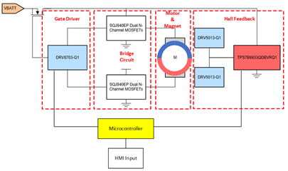
Figure 1
One form of feedback utilizes Hall-effect sensors and a ring magnet such as in this sunroof motor module reference design. The Hall-effect sensors are leveraged for encoding so the relative sunroof location can be tracked. The typical Hall-effects sensors used in this application are latches, sometimes referred to as bipolar switches. Latches have a binary output which is pulled low in response to a sufficiently strong south field, and a sufficiently strong north field triggers the output high as seen in Figure 2. As the name implies the output state latches and maintains until the opposing threshold is crossed.
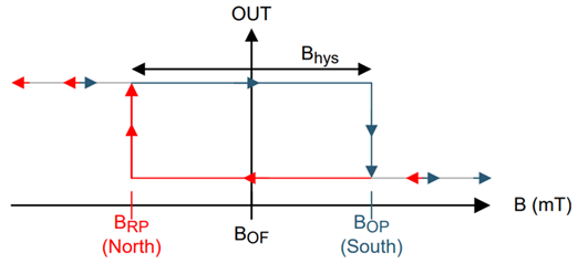
Figure 2
A multipole ring magnet on the motor shaft accompanies the Hall-effect latches. The basic principle is that while the motor turns, the magnet poles rotate past the latch. With every pole transition the magnetic flux density (B-field) observed by the sensor flips, thereby creating a train of pulses from the latch output while the motor is spinning. These pulses are directly related to motor rotations, which can then be translated into window displacement. If displacement can be discerned then relative location can also be determined after an initial calibration.
Figure 3 illustrates the B-field and corresponding output of an appropriately placed z-axis sensing Hall-effect latch next to a rotating dipole ring magnet. The green arrow indicates the direction of the strongest B-field vector. Here we can observe that when this field vector is pointed upward, the measured B-field is positive, while conversely the field vector is pointed downward, the measured B-field is negative. Here we see that when the field is sufficiently positive, the operating point (BOP) is crossed and the device output latches low until the field is sufficiently negative to cross the release point (BRP) and latch high.
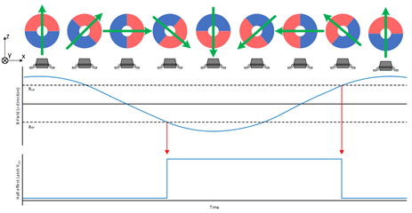
Figure 3
While a single sensor provides pulses that can correspond to magnet position, it is insufficient for situations in which the motor can move in more than one direction. Below in Figure 4 we see that a change in direction can lead to the exact measured output as in Figure 3.
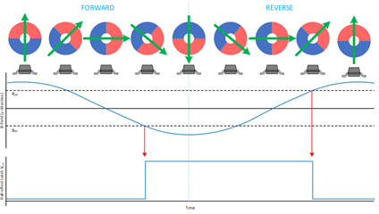
Figure 4
To combat this, we add an additional latch magnetically 90° out of phase with our first sensor as illustrated in Figure 5.
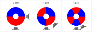
Figure 5
In Figure 6, a ring magnet changes direction after 1.5 rotations. At that point the rotation reverses direction, where we can observe a few behaviors. One behavior is that the B-field signal for Sensor 1 provides no clue that direction changed while the B-field for Sensor 2 does. Had the motor reversed elsewhere, it is possible that the B-field at Sensor 1 rather than at Sensor 2 would indicate the rotation direction changed. Another behavior we observe is that the Sensor 1 output pattern does not change, while the Sensor 2 output pattern by itself suggests the possibility that the magnet or motor rotation temporarily paused. By having both signals to compare, we can rule out the possibility of the motor pausing. In addition, having two appropriately spaced latches allows you to detect direction change when the order of the outputs’ rising or falling edges change.
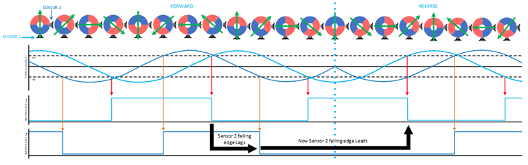
Figure 6
If the space for sensors is limited due the enclosure size, cost, or other factors, one alternative could be a 2D latch capable of simultaneously measuring two orthogonal axes, like the TMAG5110.
If you would like more detailed information on using Hall sensors for motor monitoring, including auto body applications, please read our app note TMAG511x 2D Latch Benefits.
