I am trying to use the reference design for gas sensors from Semeatech. When I am calculating the RF value based on the reference design. I am trying to figure out what changes I should make to the design with gas sensors for reducing gases like NO2 and O3 where the current generated is in negative values per ppm. Applying the same calculations with O3 or NO2 gases I am getting negative value for the RF resistor. What should be done if the calculated resistor value is negative. Please help me with the circuit changes.
| O3 Gas | ||
| Sensor Sensitivity (Isense) | -0.85 | μA/ppm |
| Max Sensor Range from Datasheet | 10 | ppm |
| Max Sensor Current (Imax) | -8.5 | μA |
| Vzero (CE headroom)* | 300 | mV |
| Max Voltage Output (Vout = Vref) | 2048 | mV |
| System Input Voltage | 3.3 | |
| Voltage Swing (Vout - Vzero) | 1748 | mV |
| TIA Resistor Rf = Vswing/Imax | -205.647 | kΩ |
| Load Resistor (RL) from Datasheet | 33 | Ω |
| Bias Voltage | 0 | V |
| Sensitivity Vsense_ppm = Rf x Isense | 174.8 | mV/ppm |
| Measurement at Zero ppm | 300 | mV |
| Measurement at Max ppm | 2048 | mV |
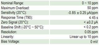
Please see specifications of Semeatech O3 gas sensor.