This thread has been locked.

If you have a related question, please click the "Ask a related question" button in the top right corner. The newly created question will be automatically linked to this question.

TDC1000-C2000EVM: I have some problems when I use TDC1000-C2000EVM measuring TOF, Can you help me?

Part Number: TDC1000-C2000EVM
Other Parts Discussed in Thread: TDC1000

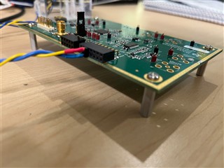
I have bought a TDC1000-C2000EVM for TOF measuring, after I solved the question of compatibility by friends' help on this website, I have a new trouble this time.

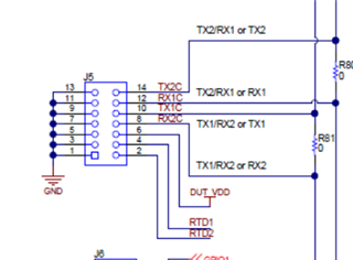
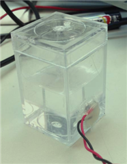
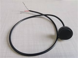
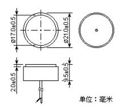
Since I use the J5 part of the TDC1000-C2000EVM, the first problem is what a transducer I should use, I read the technical documentations of TDC1000 and knew  STEMiNC’s 1 MHz transducer-SMD10T2R111, which is recommended by the TI official, but I don't have the way to buy this and just can buy a transducer named NU1M21TR-1 from China, but this transducer is not same as the former, its diameter is about 17mm, and it's very thickness. (毫米:mm)

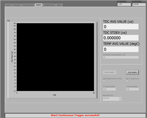
The second problem is that I don't know how to connect the pin of above mentioned transducer with the J5 part, I tried all the possibility to connect them, but just one condition there is a graph on the TDC1000-C2000EVM GUI interface, but the graaph is always a straight line though I move the transducer to many directions with different objects and TOF. But I change the TX_FREQ_DIV part of the GUI, the TOF showed by the graph change like below pictures. This operation just change the amplitude but the phenomenon that different direction have the same TOF is still exist. Noticed, when the TX_FREQ_DIV set Divide by 64 the graph stop going on, when set Divide by 32 it recover the straight line. I can't explain this phenomenon and don't know how to get a graph like the technical documentations show, which can change when the direction of transducer change or liquid content change. Is it because of the nonstandard tranducer or anyother fators like TDC1000's set?

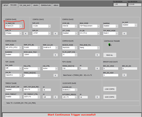
The third problem is that I have only one tranducer, so I need to use Mode 1 that transmit and receive signal by one transducer, but when I set Mode 1 on the TDC1000 interface, there will have any change on the graph interface. Only when I connect TX1 and TX2 and ground lead there has the graph, any other connect like Mode 0 with TX1-RX2 or Mode 0 with TX2-RX1 will not get graph like below picture, here I have start the TOF measurement but there is no graph on the interface.

  • Hello Songjiang,

    Thanks for posting to the PS forum. To answer your question on the transducer you are allowed to use any transducer that you would like as long as it is in the operating range of the device, just note that different transducers have different specifications and characteristics that could affect your application. So if you are looking to use something similar to the  STEMiNC’s SMD10T2R111 transducer I would make sure to get something that is rated at 1MHz and something that is just a ceramic disk or open top. Please note that we typically only recommend 1MHz-4MHz transducers on TDC1000.

    The transducer you are using looks like it could be a closed top transducer which is also acceptable but it is important to note what the differences in construction mean. The closed top means it is more protected against harsh environments but will require more voltage to drive which is not the most suitable for TDC1000 which has a very limited driving range compared to some of our other EVMs. Typically larger transducers also need more energy to excite them so this could also be an issue for the transducer you are currently using. If you would like to know more about how transducers feel free to watch this video: https://training.ti.com/ultrasonic-transducers?context=1147829-1147767

    The next question is if you are trying to make air measurements or water based measurements? TDC1000 is typically only recommended for liquid based ultrasonic measurements. If you are trying to make measurements over the air I would make a different device recommendation as well as transducer frequency. The TX_FREQ_DIV divides the provided clock frequency to match your transducers frequency. In this case its 1MHz and the provided on board oscillator is 8MHz so you want to use the divide by 8 setting.

    For the J5 connector the channels TX2/RX1 and TX1/RX2 are already connected together. When connecting to the J5 connector your ground lead has to connect back to ground and your signal wire is the one connected to the other channels.

    I hope this helps!

    Best,

    Isaac

  • Hello Mr. Lara,

    Thanks for your help for my questions, if the transducer I am using now may not suitable, I want to ask whether I can buy the STEMiNC' s SMD10T2R111 transducer from your company? I need them for my liquid TOF measuring, if you can provide the way for us to by them, please let me know their price and the time they arrive our location, the city Xi'an in Shaanxi Province, China.

    Looking forward for your reply!

    Sincerely, 

    Songjiang 

  • Hello Songjiang,

    If you the transducer to not be suitable for your application then you can always find another that is better suited for your application. Unfortunately TI does not sell these transducers, looking at the transducer manufacturers website it looks like you can purchase them directly from the STEMiNC and it seems they do ship overseas: https://www.steminc.com/PZT/en/shippinginfo

    Best,

    Isaac

  • Hello Mr. Lara,

    Thanks for your reply, I will to contact with the STEMiNC's official to ask the details.

    Sincerely,

    Songjiang

  • Hello Mr. Lara,

    I am sorry to disturb you again for a question I have think of today, you said that I need to connect the ground lead back to ground when I use J5 connector, but I noticed the pictures from the TI technical documentations, they showed the SMD10T2R111 connect only two leads, maybe TX and RX, like the picture below, I want to ask if I can buy the STEMiNC' s products successfully, how can I connect them with J5 connector.


    I also want to know the connect details of the leads and TDC1000-C2000EVM board, could you please provide me with a  picture of real object?

    Looking forward for your reply!

    Sincerely, 

    Songjiang 

  • Hello Songjiang,

    I hope you are able to get some transducers. To answer your question the black lead is ground lead, and the red lead is both the TX and RX lead. The pin in which it is connected to the J5 connector depends on which Mode is selected on the device. For TOF_MEAS_MODE = 0 and CH_SEL = 0 you can connect it like the picture below:

    The transducer in this image is yellow for TX/RX and blue for GND, but I put some red tape on the signal wire for clarity.

    I hope this helps!

    Best,

    Isaac

  • Hello Mr. Lara,

    Thank you very much for your help! 

    Sincerely,

    Songjiang

  • No worries Songjiang, glad to help out!

    Best,

    Isaac