This thread has been locked.

If you have a related question, please click the "Ask a related question" button in the top right corner. The newly created question will be automatically linked to this question.

IWR6843AOP: I2C Configuration registers Slew Rate and Pull Up register status check

Part Number: IWR6843AOP

Hello Community,

I am trying to set pull up set high and slew rate high for my I2C configuration. I could do it with functions "Pinmux_Set_Pull()" and "Pinmux_Set_SlewRate()".

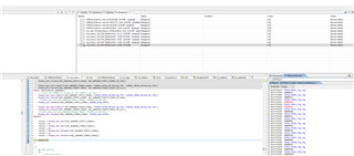
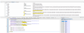
I could see pull ups and slew rate getting set from functions "Pinmux_Get_Pull" and "Pinmux_Get_SlewRate" as shown in figure.

But when I read configuration register in debug could not see values getting reflected on Pull up select register and slew rate select register. 

Are those the correct registers to see if pull ups and slew rate has been set correctly ?

Thanks and Regards,

Neil

  • Hi Neil,

    I am looking into this a bit  further to see if these fields in the I2C registers are meant to be updated. In the meantime, I believe these changes should be reflected in the IOMUX registers for PADxx_cfg_reg. Let me know if you see any issues regarding the functionality of the I2C when using these settings.

    Best Regards,
    Alec

  • Hi Alec,

    Yes the changes get reflected on IOMUX registers, as you can see in figure.

    The behaviour on I2C bus is shown in figure below. I don't know why clock looks like this on analog signal. It couldn't reach till 3.3V and the response looks like saw tooth wave. This is when IWR6843AOP is not connected to external I2C interface device at 400khz. I have just tested I2C ports via logic analyzer when ports are open. Is this the normal behaviour of device ? 

    Thanks and Regards,

    Neil

  • Hi Neil, 

    Understood. Please allow me to briefly look into this  and get back to you

    Best Regards,
    Alec

  • Neil,

        Is this happening on IWR6843AOP EVM or custom hardware? Logic analyzer will not reflect correctly voltage levels as that of oscilloscope. It's better to get the screenshot of the I2C lines during the transaction. Also good to check values of pull up resistors. 

    Thanks and regards,

    CHETHAN KUMAR Y.B.

  • Hello Chethan,

    This is happening on IWR6843AOP EVM. Below shown is the screenshot of I2C lines during communication. Pull up on temperature sensor are of 1k on SCL and SDA whereas on IWR6843AOP its 10K. So in parallel it makes 0.9k.


    Thanks and Regards,

    Neil

  • Neil,

       While checking on the temperature sensor schematic, couldn't see pull up resistors, could you please confirm?    

        Could you please provide the LA/Oscilloscope instrumentation will not have good vertical resolution, It would be good to get conventional Oscilloscope screenshot to see steady state & transient values of SDA/SCL lines. 

    Thanks and regards,

    CHETHAN KUMAR Y.B.

  • Chethan,

    Thank you for your reply. Here you can see 10K pull ups connected to output from PMIC. 

    But I will also check the output from Oscilloscope.

    Thanks and Regards,

    Neil

  • Neil,

        Thanks for the confirmation, I was wondering how effective pulls become 0.9k.  Yes checking with the Oscilloscope provides better voltage resolution. 

    Do you have any other board/interfaces connected to the EVM? While probing on the scope it's good to remove all the LA probes to ensure there is no loading on the I2C lines. 

    Thanks and regards,

    CHETHAN KUMAR Y.B.