This thread has been locked.

If you have a related question, please click the "Ask a related question" button in the top right corner. The newly created question will be automatically linked to this question.

TMAG5170-Q1: Built-in Diagnostics

Part Number: TMAG5170-Q1
Other Parts Discussed in Thread: TMAG5170

I have several questions about the diagnostics built into the TMAG5170.

  1. When and how are the diagnostics executed?
  2. Do the diagnostics settings affect the power consumption of the part? The current specifications in the datasheet don't mention this, but in section 7.4.1.1 it suggests the conversion time depends on the diagnostic settings.
  3. Is there a recommended procedure to perform a self-test of the device?
  • David,

    A high level discussion of many of the diagnostic features appears in section 7.3.7 of the datasheet.  Each individual check does contain information regarding how it is run, and what can be done to configure it.

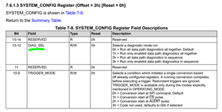
    The DIAG_SEL register setting configures how the diagnostics are set to run together, and you do have the ability to configure the run method and which diagnostics are captured.

    For a more complete guide regarding how to configure these various settings to suit your specific needs, I recommend requesting the ISO26262 Functional Safety documents from the link at the TMAG5170-Q1 product folder page:

    https://www.ti.com/licreg/docs/swlicexportcontrol.tsp?form_id=326107&prod_no=TMAG5170Q1-FSDOCS&ref_url=asc_sensing

    The guide will provide a thorough explanation of the various diagnostic features and how they run in better detail than I could provide here.

    Thanks,

    Scott

  • I've asked for access to the ISO26262 document. When (if) I get it, I'll review it to see if that answers my questions 1 and 3. Apparently, I won't get access for a couple of days so I'll keep the issue open until then.

    In regards to question #2, does enabling the diagnostics (SYSTEM_CONFIG.DIAG_EN) increase the device power consumption? Maybe it's in the ISO document, but is it expected that the device will always be operated with diagnostics enabled?

  • David,

    The major concern with adding in the diagnostics will be the additional time to allow for those to complete.  During the diagnostic checks there should be no increase in current.  The primary current draw for this device occurs while the device is actively converting using the Hall-elements.  The default condition for the device is that that the AFE diagnostics set by DIAG_EN are disabled:

    Diagnostics are optional, and not needed in all applications.  They should be enabled when trying to design towards ISO26262 standards, however.

    Thanks,

    Scott

  • Just to keep you updated, I'm still waiting to get access to the ISO26262 document. Once (if) I'm approved, I'll look at the materials and see if that answers my questions.

  • David,

    Were you able to submit the access request from the product page? If you have not done so yet, please use this link to submit your request.

    https://www.ti.com/product/TMAG5170-Q1

    Request more information: 

    The ISO26262 compliant functional safety documents for TMAG5170-Q1 are available. Request now

    Thanks,

    Nayeem

  • Yes, I submitted it back on March 11th. I may have submitted it again last week. Maybe I forgot to hit "Send" the first time?

  • I finally got approved for the ISO26262 document and it does, indeed, answer my questions. Before I mark this thread "resolved," let me submit a few comments for other TMAG5170 users who may be wondering the same things.

    • If you really need super-reliable operation and want to use the diagnostics in this chip, register to get a copy of the ISO document.
    • The AFE diagnostics can significantly increase the sampling time. If you're not prepared to handle the diagnostic failing, I would suggest running with SYSTEM_CONFIG.DIAG_EN set to zero. If you are still interested in the diagnostics, run with SYSTEM_CONFIG.DIAG_SEL = 0b1x. This will only add about 20-25 µs to the conversion time for each conversion set.
    • The AFE diagnostics perform many ADC conversions as well as increasing the conversion time so the power consumption is definitely higher.
    • It seems like a suitable POST procedure would be:
      • Read and write the DEVICE_CONFIG register and verify that you can access the registers.
      • Test the oscillator
      • Perform one magnetic sample with diagnostics enabled. This will ensure that the analog circuitry is okay (at least on power-on). If you set up the chip to interrupt on sample complete (ALERT_CONFIG.RSLT_ALRT is set), then you can check the INT pin state.