This thread has been locked.

If you have a related question, please click the "Ask a related question" button in the top right corner. The newly created question will be automatically linked to this question.

BOOST-LDC3114EVM: What is the minimum capacitance change that the LDC3114 can measure?

Part Number: BOOST-LDC3114EVM
Other Parts Discussed in Thread: LDC3114, FDC2214

Dear TI experts,

Based on this application report (https://www.ti.com/lit/an/snoa970/snoa970.pdf), I want to use the LDC3114 to measure the capacitance change of a parallel plate capacitive sensor at frequencies of 5, 10, 15, 20, 25 and 30 MHz.

Applications mainly involve measuring changes in relative permittivity and conductivity of the complex dielectric at different frequencies.

The capacitance change tested by the FDC2214 is approximately 0.01 to 0.1pF at 3MHz. However, since FDC can only go up to 10MHz, for testing at higher frequencies, LDC was considered.

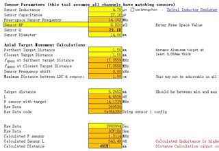
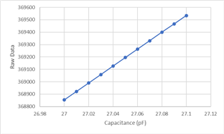
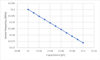
So my question is how do I know the minimum capacitance change that the LDC3114 can measure?

Also, the LDC3114 has an input pin capacitance, does this need to be taken into account when calculating the expected oscillation frequency?

Best regards,

Will

  • oBouyan,

    All of the LDCs actually measure a change in the resonant frequency of the LC-based sensor.
    To answer your last question first, yes, it makes sense to take the input capacitance into account if it is within 5%-10% of the value of the total external capacitance on the input pins.

    The smallest capacitance you can measure will depend on the sensor configuration and the LDC device settings.
    I have never tried it before, but I think you can use the Inductive Sensing Design Calculator Tool to answer to your question.

    It will be kind of a "hack". but it is worth a try.

    Download the spreadsheet tool and go to the tab LDC3114_Config_Tool, and scroll down to the bottom of that page until you see the section Sensor Parameters.
    Enter nominal values for the sensor inductance, capacitance, and Rp. Then set a Target Distance that is related to your application.

    Try "small" increments of the Sensor Capacitance values and note the value changes in the Raw Data value in that field (w/orange fill). 

    The smallest increment in the sensor capacitance that will result in a desired change in the Raw Data code will be the smallest capacitance you can measure with that LC sensor.
    This is still kind of ideal. 
    The next step will be to find the device settings that will support those sensor settings. The upper part of the LDC3114_Config_Tool, tab can help with that.

    We have some on-line blogs that give background on the tool's use.
    One blog can be found here, and the other can be found here.

    You can find a number of helpful blogs and FAQs on inductive sensing at the Inductive Sensing Blogs page.

    Regards,
    John

  • Thanks John,

    I tried using the settings in the figure below.

    Here is the result I got.

    It seems like a 0.01 pF capacitance increment can shift 0.0025MHz in frequency, 72 in the raw data.

    In your experience, whether this is above the LDC3114's noise floor or still requires some practical testing.

    Best regards,

    Will