This thread has been locked.

If you have a related question, please click the "Ask a related question" button in the top right corner. The newly created question will be automatically linked to this question.

HDC2010: Randomly we read 0%rh and 0°C or 0%rh and -40°C from the HDC

Part Number: HDC2010
Other Parts Discussed in Thread: HDC2080

Hello Everyone

We develop an roomthermostat with an HDC2010, we have about 100 ore more prototypes.

We use the HDC in Automeasurement Mode both(humidity and temperature) in 14bit, 1 sampe per minute, only the dataready interrupt is enabled

at only one device we had troubles, sometimes, once per Hour or  Day, we read from the HDC wrong values 0x0000 ore 0x0001 for Humidity and Temperature, with the next measurement the values are okay.

the 0x0000 we detect in our firmware, for this case we work with the old value, that is okay for us. but the 0x0001 we don't detect in the moment an we didn't know if it is always 0x0000/0x0001 or sometimes also an other wrong value (0x0002?).

How we can handle this error, so that the roomthermostat don't show 0%rh and -40°C on the integrated Display?

Thanks in advance

  • Dear Loris - 

    The HDC20x0 devices have a firmware behavior selectable pin named DRDY/INT. The purpose of this pin is to provide an interrupt back to an MCU with interrupt capable GPIO (to allow MCU to sleep in between sensor measurement) or polled GPIO (if MCU not sleeping) when the HDC20x0 device is placed in automatic measurement mode, after a measurement has been completed, to wake up the MCU and trigger a read of the registers 0x00 through 0x03 routine. 

    If you are using DRDY/INT, you should ensure that you write register 0x07 with 0x80 and then write register 0x0E for setting the automatic mode of choice. Then it would be recommended to read register 0x04 for 0x80 (data ready) after the interrupt fires, to have a redundant check that new data is ready, before reading out temperature and humidity registers. If you did not route the DRDY/INT line due to unknown constraints, or design is using one-shot mode, I would recommend at least reading register 0x04 for a value of 0x80 before reading out temperature and humidity registers, to avoid getting values asynchronously, which in your case is giving you empty values. 

  • Dear Josh

    Thanks for Answering.

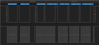
    We write to the register 0x07 the value 0x80 and to the register 0x0E the value 0x26. Attached you can find the Capture of the Startup procedure.

    The DRDY/INT Pin of the HDC is connected to our MCU and generates an external interupt on the MCU, and we read the register 0x00 - 0x03 only after we detected the interurpt. It tooks 6.5ms between the rising edge of DRDY signal an the I2C command to read out the values.

    The recommended check of register 0x04 is in the moment not implemented, but i will do.

    HDC2010_startUp_logicdata.zip

  • Dear Loris - 

    I did this on HDC2080, but its identical to HDC2010. 

    This capture of how to set it up - here I set 0x07 to 0x80, then set 0x0E to 0x56 (in your case it is longer interval), then (in this case, I read out all the registers starting with 0x04) - you don't need to do this, then I sent start conversion and then firmware waits for interrupt, then reads out 0x04 for 0x80, then reads temp and %RH registers (0x00 through 0x03)

    Also here is the capture in case the images are not good. 

    HDC2080_HDC2010_comparison_DRDY.logicdata

  • Dear Josh

    Yesterday im implemented the reccomended check of register 0x04, but this do not solve my issue. In case i read 0x0000/0x0000 from the HDC, the DRDY_STATUS bit, TL_STATUS bit and the HL_STATUS bit is set. As you can see in the picture.

    For me it looks like the HDC means that the measurements is finished and the values are okay. This sample is located in my office by approximately 24.5°C and 35%rh.

  • Loris - 

    are you triggering on DRDY/INT or waiting time? If waiting time, you have to wait >1.3mSec before reading (for first read this is the case, because after setting up the device and issuing start conversion, the first measurement will be ready in that time) - after that, you should wait for 0x80. Best way is to trigger on DRDY/INT line, read 0x04 for 0x80, then read out 0x00 - 0x03. 

  • Dear Josh

    We triggering on the DRDY/interrupt, not on Waiting time! after the rising edge of the DRDY Signal, our Firmware needs 6ms befor we read out the registers.

    The failed measurement is not the first measurement, in this case it was after 2 hour, we read out the sensor every minute. I will attache the capture, the Failsequence is by timestamp 10312s :525ms. After the failsequence, we do a softreset of the HDC and reconfigure him. HDC_DRDY flag set an 0x0000.zip

    This failure we saw only at one Device, the other 100 Devices workings with the same Firmware as expected.

  • Loris - 

    I see what you are saying in the capture - I would not use soft reset at all, and I am not sure what happened in between that last good read and you getting 0xA8, then reading out 0x00 0x00 in the temp & %RH registers. What I have done to avoid this altogether is to not proceed to reading 0x00-0x03 unless 0x04 is 0x80. You could also read out all the registers when you get 0xA8 like that, for further troubleshooting, if that is possible. 

  • Dear Josh

    Sorry for the delayed Answer. But it taks some time to capture the error again.

    I implementet in our HDC routine, that we read all registers from the HDC, if the register 0x04 ist set to 0xA8.

    if i see coorect, the register 0x0F Measurement Configuration is set to 0xF6, that is a incorrect value, but we write in our configuration routine 0x01 to this register. How this can happen? I don't write to this register since the last good measurement. All other register have an plausible value.

    See attached capture, timestamp 13960s : 276ms

    Read all registers on Error Capture.zip

  • Dear Loris- 

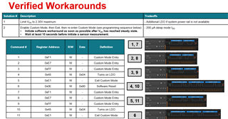
    As I said, sending the reset to the part is not recommended (0x80 to 0x0E). In this case, you must have some slightly older devices (which we fixed about a year ago) which had an issue where above 2.3VDC, the devices had a possibility to have register corruption.  Please use this firmware workaround when you see anything but 0x00 in register 0x0F. 

    https://e2e.ti.com/support/sensors-group/sensors/f/sensors-forum/1008725/hdc2080-faulty-0x0f-register-initialization-with-2-3v-custom-command-sequence?tisearch=e2e-sitesearch&keymatch=HDC2080%2520register# 

  • Dear Josh

    Thanks for this answer.

    do i understood correct if i read after powerUp 0x00 in register 0x0F then it is a new device, if i read something different to 0x00 from the register 0x0F after PowerUp then it is an old device, -> i have to use this special configure routine. if i use the special configure routine to new devices, are there negativ effects?

  • Dear Loris - 

    the only slightly negative here is that after running the workaround, as long as power is applied and software reset is not applied, the part will draw 200uA constantly, as what the workaround does is turn on sub regulator in the device, reset the part in known good state, then turn the sub regulator back on, to ensure the issue does not occur. 

  • Dear Josh

    That means the device will consume 200uA instead of the 50nA in Sleep, for the hole time the device is powered? Our PCBA is battery (CR2032) powered, this increased power consumption is not okay for our application. We don't have the option to remove the power from the HDC. Is there a other firmware workaround? we had parts for one year in the storage.

    Thanks in advance

  • Dear Loris - 

    This is the workaround with those vintage parts. The only thing you could do is reset the device with 0x80 to register 0x0E, then the part will go into shutdown normally, but then you run into the possibility of this occurring again. The only other thing I can think to do here is to read the registers (0x04 to 0x0F) periodically and only run the workaround when those are not default values.