This thread has been locked.

If you have a related question, please click the "Ask a related question" button in the top right corner. The newly created question will be automatically linked to this question.

AWR6843ISK: Design Inquiry

Part Number: AWR6843ISK
Other Parts Discussed in Thread: MMWAVEICBOOST, IWR6843

Hello Team,

I'm posting this on behalf of my customer:

We purchased the AWR6843ISK module and we want to use it to detect drones.
We want to be able to detect successfully the drone propellers by their doppler signature in order to achieve good classification from a bird or a tree.

Our questions are:

1. Can you offer us a recommended way of achieving this adaptation?
2. We watched the video “mmWave Radar Programming Model”
(https://training.ti.com/mmwave-radar-programming-model) that explains
how to program the mmWave Front end block using the API’s method.
But we assume that in order to achieve our goal we need to get access to the
yellow block “mmWave processing” described in the attached image.
How do we get access to this block?
How to program this block?
Is the programming of this block done by C code or by API’s?

To be clear again: in the block “mmWave processing” we want to be able to
change by software the condition on the doppler filter to achieve classification ability.

Regards,

Renan

  • Hello Renan,

    Please have them look at the SDK doxygen information for information on the processing in the OOB demo. The source code is available in the SDK and in the industrial toolbox download on TI Resource Explorer.

    "C:\ti\mmwave_sdk_03_05_00_04\docs\mmwave_sdk_module_documentation.html"

    https://dev.ti.com/tirex/explore/node?a=VLyFKFf__4.10.1&node=AJoMGA2ID9pCPWEKPi16wg__VLyFKFf__4.10.1

    Regards,

    Jackson

  • Hello Jackson, 

    Please see response from my customer:

    We purchased the AWR6843ISK and the MMWAVEICBOOST and we have several questions:

    1. We want to be able to detect successfully the drone propellers by their doppler signature in order to achieve good classification from a bird or a tree.
    Can you offer us a recommended way of achieving this adaptation?

    2. We want to know where is the code (which file contains it) that responsible of the signal processing of the radar in order to change the sensitivity of the doppler signature.

    3. We followed the steps described here: dev.ti.com/.../node
    and after we clicked "Rebuild project" on "mmwave_sdk_68xx_hwa" we faced this CCS error (screenshot attached).

    Regards,

    Renan

  • Hello Renan,

    Please make sure you have gone through the user guide documentation to understand how to run and rebuild the demos. Please make sure you have all the required packages mentioned.  

    https://dev.ti.com/tirex/explore/node?a=VLyFKFf__4.10.1&node=ALrLWv8piSenPXIAWScBow__VLyFKFf__4.10.1

    The link in the previous post has info on modifying the configuration file for doppler sensitivity. For getting a unique profile you will need to adjust the velocity resolution of the chirp. Please see the following document for info on setting chirp parameters.

    Programming Chirp Parameters in TI Radar Devices (Rev. A)

    Regards,

    Jackson

  • Hello Jackson,

    Thank you for your answer. Please see the update from them below:

    We would like if you will make us things a little bit more clear:

    1. We understand the programming method of profile configuration, however we would like to know where is the actual code that responsable of the signal processing of the radar.
    That is because we do not want to just distinguish between two velocities but to distinguish between them and filter out one and keep the other.
    Our final goal is to fly a drone in front of the radar and we want the radar to detect only its propellers and not the body of the drone.

    2. In the "mmWave Demo Visualizer" what causes an orange dot to appear on the 2D scatter plot?
    We mean what are the software conditions, the thresholds needed in order to an orange dot to appear?
    How we can access those thresholds or conditions and change them?

    3. When we tried to install the "ticloudangent" in order to use "mmWave Demo Visualizer" on a macbook laptop
    we got this black setup window (screenshot attached).
    This is a 2020 M1 fully updated macbook that we managed to use the "mmWave Demo Visualizer" on it two month ago
    but right now it forces us to reinstall the "ticloudangent" and leads us to this black window.

    Regards,

    Renan

  • Hello,

    There are many locations where the signal processing takes place, as there is a lot to process. I suggest you look at the demo documentation for how it functions. You will want to look in the SDK DPC and DPU folders for where the processing takes place. Please see the following links.

    SDK Deep Dive
    C:/ti/mmwave_sdk_03_05_00_04/docs/mmwave_sdk_module_documentation.html

    For using TI Cloud agent on Mac, please make a new question, it will be directed to a different team.

    Regards,

    Jackson

  • Hello Jackson,

    Please see below the latest response from my customer:

    After exploring myself during this time I have now more accurate technical questions:
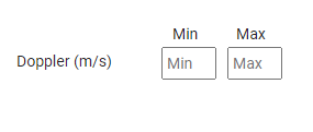
    1. I noticed that in the mmwave demo visualizer there is an option to create a Low Pass Filter to the velocity as described in the attached screenshot. For example if we insert Min=-20 Max=20 I noticed we get a LPF from 0 to 20 m/s on absolute value.

    So what we are want to do is to create a High Pass Filter of velocities. For example we want to choose 20 m/s as our cutoff velocity so all the objects that move under 20 m/s will be filtered out and all the objects that move above 20 m/s will be detected.

    What is the best way to execute that?

    2. 2. We followed the steps described here: dev.ti.com/.../node
    and after we did "Rebuild project" on "mmwave_sdk_68xx_hwa" and after triple check, we performed all requirements we faced the attached CCS error.
    How to solve it?

    Regards,

    Renan

  • Hello,

    To go back to a previous question, the yellow dots on the range profile indicate points that have met the threshold criteria to be included in the pointcloud. These will be determined mostly by the CFAR thresholds and parameters, although all stages of the processing contribute. I suggest to look at the CFAR section of the doxygen documentation.

    For the doppler filter, there are two ways. The first is to simply filter the UART output list. Either by sorting and removing in the UART output function, or by processing when the data is received by the host. However this will not change the underlying processing. To really make the filter you are looking for, you will need to change the behavior of the CfarFovCfg command in code. you can see that when changing the doppler filter boxes in the GUI, a new CfarFOV command is sent. Right now the functionality you are looking for is not built into the SDK, but can be added if you trace where the filters are being applied in the code.

    For the build errors, this could be a few things.
    1) DId you modify the source code at all? If so, please try reimporting and building without any changes just to test the build environment. But I think this is already likely the case.
    2) Are you sure the XDC tools is downloaded properly to that folder and that it is installed in CCS in the window>preferences>code composer studio>products window.

    Regards,

    Jackson

  • Hello Jackson,

    Please see response from my customer:

    1. What do you mean by "can be added if you trace where the filters are being applied in the code", in which code to look for? which filters to look for?


    2. We read the document: training.ti.com/.../mmWave_Radar_Programming_Model.pdf
    And we understand it's content but our question is where are we supposed to apply it? In which file/code are we able to define those configurations?

    3. The attached screenshot describes the configuration code as we downloaded it from the "mmWave demo visualizer". This file contains configuration commands that appear in the document in question 2 but also some commands that do not apear there, like "cfarFovCfg", "cfarCfg", "clutterRemoval" and more… So where can we find the configuration guide for these commands?


    4. About the buiId error- I did not modify the source code at all and I think the XDC tools is downloaded properly, take a look in the attached screenshot

    Regards,

    Renan

  • Hello,

    1) I suggest you start in mmw_cli.c and see what parameters are being modified by the cfarFovCfg. This way you can see all the locations these filters are applied. Likely they will only be applied in cfarcaprocdsp.c. You may need to open these in some editor like VS code so you can search many files. The cli commands will start in the demo from the toolbox, but the underlying code will be in the SDK folder. 

    2) This is a very old document, made before the recent demo structure. This is mostly handled in the CFG file you linked above. You will see the profileCfg and other commands that match to what was in the document. The API level is already handled by the demo.

    3)The documentation for all these commands will be in the SDK users's guide. typically found here: "C:\ti\mmwave_sdk_03_05_00_04\docs"

    4)Can you confirm which version of CCS you are using? Also, after building are there any errors in the problems window in CCS? Or are the log errors the only ones? Can you please send the entire error message? The screenshot only has some.

    Regards,

    Jackson

  • Hello Jackson,

    Please see my customer response below:

    The console window and the problems window are attached

    Regards,

    Renan

  • Hello,

    I see now, I didn't realize you were building the auto toolbox projects. Those have an issue and are broken right now. Please use the OOB demo from the industrial toolbox, those will build. The documents may indicate IWR6843, but the projects will work exactly the same for the AWR device.

    https://dev.ti.com/tirex/explore/node?a=VLyFKFf__4.10.1&node=ALrLWv8piSenPXIAWScBow__VLyFKFf__4.10.1 

    Regards,

    Jackson