This thread has been locked.

If you have a related question, please click the "Ask a related question" button in the top right corner. The newly created question will be automatically linked to this question.

PGA970: PGA970EVM Wave No Longer being Generated

Part Number: PGA970

Hi Team,

I just started working with the PGA970EVM board and initially the board was generating waveform at PI (TP16) with no LVDT attached.  I was able to change the frequency so I know the SPI interface was working.  After a power down/up of the board, the waveform is no longer being generated.  Just getting a flat line at TP16.  Tried different waveform generator setting but no difference.

Measured board voltages are shown below.  I notice REFCAP (TP17) is 0 volts, not sure what it should be?

DVDD (TP9) 1.85v

AVDD (TP6) 2.99v

REFCAP (TP17) 0v
Thanks -Chris

  • Hi Chris,

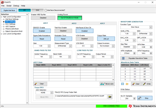
    The VREF buffer should be enabled, and when it is you should see 2.5V on the REFCAP pin. The waveform DAC is referenced from the output of the VREF buffer, so you will not see an output if the VREF buffer is disabled.

    Regards,
    Scott

  • Hi Scott,

    Thanks for the response.  I enabled the VREF butter and now getting 2.5v REFCAP (TP17).

    I still am not getting any waveform generated at PI (TP16)?  I noticed I am getting about 11v DC at the primary (TP70,TP71)?

    I would appreciate any other suggestions you have that I may try or looks at.

    Thanks,

    Chris

  • Hi Chris,

    Do you see a DC voltage on PI or P1(one)? It seems like the amplifier circuit for the primary drive is possibly railed out to the VPWR voltage that you're supplying to the EVM. 

    And just for to be certain, it looks like you've populated the waveform table with the settings, but have you then written that waveform data to the waveform ram before starting the generator?


    Regards,

    Scott

  • Hi Scott,

    I see11.2 volts on P1(one) (TP70).   Nothing on PI, just flat-line 0v.

    Did write down the waveform data table and it appears to transfer OK.  Powering the board with 24v and measured voltages  DVDD (1.85v), AVDD (2.99v) and REFCAP (2.5v) look good.

    Not sure what to try at this point, like I said it was initially generating the waveform but failed after restart.

    Any further test you can recommend would be appreciated.

    Thanks,

    Chris

  • Hi Chris,

    Did you make any other changes to the FRAM in the meantime, like programming your own firmware into the device? Or was the only change made to the waveform data, which initially worked, and did not after restart?


    Thanks,

    Scott

  • Hi Scott,
    Only made change to waveform data.   Really just started working with the board, was able to generate the waveform and change the frequency and see it on my scope (PI), then lost it after power up.
    Is there way to tell if FRAM got changed/corrupt form default?
    Thanks,
    Chris
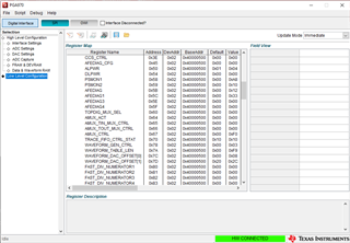
     waveform registers values
  • Hi Chris,

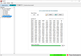
    You can check the waveform RAM data from the Data & Waveform RAM page, but unless you have the original one to compare against it might not be helpful. You can at least see if it's pulling the data from the FRAM properly.


    Regards,

    Scott

  • Hi Scott,

    The Data & Waveform Ram did populate with values when read.  As you said, not sure what the values mean or correspond to.

    Would you recommend loading new HEX file to the FRAM?  If so, is there a generic HEX file I can download or generate to use?

    Thanks,

    Chris