This thread has been locked.

If you have a related question, please click the "Ask a related question" button in the top right corner. The newly created question will be automatically linked to this question.

AWR1843BOOST: Setting cfg using Visualizer

Part Number: AWR1843BOOST
Other Parts Discussed in Thread: AWR1843, UNIFLASH

Hello, I have a question on Visualizer.
Edit the cfg file profile_3d.cfg in C: \ ti \ mmwave_sdk_03_05_00_04 \ packages \ ti \ demo \ xwr18xx \ mmw \ profiles
It was loaded by [LOAD CONFIG FROM PC AND SEND].

-------------------------------------------------- -------------------------------------------------- ------------
Changes
channelCfg 15 1 0
(Only one transmitting antenna is valid)
-------------------------------------------------- -------------------------------------------------- ------------

However, then nothing was displayed on the horizontal plot screen.
Is there any cause?
(See figure)

p.s.
By the way, Set up Details is set with the following configuration.
platform xWR18xx
SDK Version 3.5
Antenna Config 4Rx, 3Tx

  • Hi

    Does the visualizer work without the changes to the profile file?

    Do you see in the visualizer if the commands are received by the target?

    Thank you

    Cesar

  • Hello, thank you for your reply.

    > Does the visualizer work without the changes> to the profile file?

    Yes, it works well even if you haven't changed anything in the profile_3d file.

    > Do you see in the visualizer if the commands are received by> the target?

    I'm sorry, I didn't confirm that.
    Should I check the Console on the Setting tab?

  • Yes,

    The console should show you if the commands are received by the target

    thank you

    Cesar

  • Hello, I'm sorry for the late confirmation.
    Looking at the console screen, I think it is reflected.

    -------------------------------------------------- -------------------------------------------------- ------------------------
    mmwDemo: /> channelCfg 15 5 0
    Done
    -------------------------------------------------- -------------------------------------------------- ------------------------

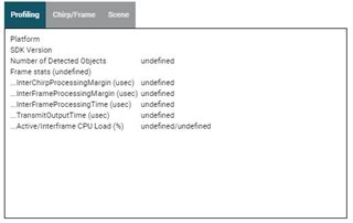
    I felt that another cause was that the Profile tab part was Undefined.

    Please reply.

  • Hi,

    The demo does not seem to run properly on the sensor.

    Could you please

    • re-flash the demo on the sensor
    • Connect the power
    • Start a Serial Terminal and connect to User COM port at 115200
    • Type enter
    • Do you see the cmd prompt?

    Thank you

    Cesar

  • Thank you for your reply.
    I will check it.

  • Thank you

    Cesar

  • Hello, the connection between Visualizer and AWR1843 Boost is slow depending on the day.
    (If it is long, even if you wait 10 minutes or more, the connection will be displayed.)

    I think it is due to the setting of Serial Port Configuration.

    For the time being, I connected the port numbers as instructed in the User Guide.

    At this time, does the baud rate of Device Manager (UART on the PC side) need to be the same as the baud rate set in Serial Port Configuration?

    Also, if there are other causes, please let me know.

  • Hi,

    This is very strange. I never experienced such low communication between visualizer and target.

    The baud rate used on the PC must be 115200 for Application UART and 921600 for Data UART

    Thank you

    Cesar

  • thank you for your reply.

    On my computer, COM4 and COM5 correspond to CFG_Port and Data_Port, respectively.

    However, COM4 can only be adjusted to 115200 (this is the same as the Baud Rate recommended in the Option tab), and COM5 can only be adjusted up to 128000.

    In this case, should I match the Baud Rate of COM5 with the Baud Rate of Option Tab?

  • By the way, is it okay to change the Baud Rate on the Option tab to 115200 etc.?

    Even if I check the Baud Rate in the device manager of my PC, the maximum is 128000.

  • How can I change the UART change speed of AWR1843 Boost?

  • By the way, is it okay to change the Data Port of Visualizer to 115200?

    If I change it, do I have to change the part of the code you showed me?

  • Yes, you would have to change in the target code the baudrate of the Data Port and re-build the demo.

    Thank you

    Cesar

  • Hi, Thank you for your reply!

    Please tell me the way of re-build the demo.

    P.S.
    Doesn't it mean that you can't connect to Data_Port just by setting the Data_Port of Visualizer to 115200?
    (By the way, the baud rate of the data port of the PC is 115200.)

  • Hi,

    In order to re-build and re-flash the demo please see the instructions in the user guide

    C:\ti\mmwave_sdk_03_05_00_04\docs\mmwave_sdk_user_guide.pdf

    Section 4.5.1 Build Instructions

    thank you
    Cesar

  • Hello, I built the demo file by following the steps in 4.5.1.

    I changed config-> loggingBaudRate in mss_main.c to 115200 and built it.

    I flashed the demo.bin file to AWR1843 Boost using UniFlash.

    After changing the baud rate of the Visualizer data port to 115200, the connection does not connect.

  • Hello, I changed the contents of profile_3d.cfg to the following to enable only Tx2.

    % Carrier frequency GHz 77
    % Ramp Slope MHz / us 100
    % Num ADC Samples 256
    % ADC Sampling Rate Msps 7.2
    % ADC Collection Time us 35.56
    % Extra ramp time required (start time) us 3
    % Chirp time (end time --start time) us 36
    % Chirp duration (end time) us 39
    % Sweep BW (useful) MHz 3555.56
    % Total BW MHz 3900
    % Max beat freq (80% of ADC sampling rate) MHz 5.76
    % Max distance (80%) m 8.64
    % Range resolution m 0.042
    % Range resolution (meter per 1D-FFT bin) m / bin 0.042
    %%
    % Inter-chirp duration us 7
    % Number of chirp intervals in frame --96
    % Number of TX (TDM MIMO) 3
    % Number of Tx elevation antennas 0
    % Number of RX channels --4
    % Max umambiguous relative velocity kmph 25.41
    % mileph 15.88
    % Max extended relative velocity kmph 76.23
    % mileph 47.64
    % Frame time (total) ms 4.416
    % Frame time (active) ms 3.744
    % Range FFT size --256
    % Doppler FFT size --32
    % Radar data memory required KB 400
    % Velocity resolution m / s 0.44
    % Velocity resolution (m / s per 2D-FFT bin) m / s / bin 0.44
    % Velocity Maximum m / s 7.06
    % Extended Maximum Velocity m / s 21.17
    % Maximum sweep accorss range bins range bin 0.74
    %%
    sensorStop
    flushCfg
    dfeDataOutputMode 1
    channelCfg 15 2 0
    adcCfg 2 1
    adcbufCfg -1 0 1 1 1
    lowPower 0 0
    profileCfg 0 77 7 3 39 0 0 100 1 256 7200 0 0 30
    chirpCfg 1 1 0 0 0 0 0 0
    chirpCfg 2 2 0 0 0 0 0 0
    chirpCfg 0 0 0 0 0 0 0 2
    frameCfg 0 0 32 0 100 1 0
    guiMonitor -1 1 1 1 0 0 1
    cfarCfg -1 0 2 8 4 3 0 15.0 0
    cfarCfg -1 1 0 4 2 3 1 15.0 0
    multiObjBeamForming -1 1 0.5
    calibDcRangeSig -1 0 -5 8 256
    clutterRemoval -1 0

    compRangeBiasAndRxChanPhase 0 1 0 1 0 1 0 1 0 1 0 1 0 1 0 1 0 1 0 1 0 1 0 1 0
    measureRangeBiasAndRxChanPhase 0 1. 0.2

    aoaFovCfg -1 -90 90 -90 90
    cfarFovCfg -1 0 0.25 8.64
    cfarFovCfg -1 1 -7.06 7.06

    extendedMaxVelocity -1 0

    CQRxSatMonitor 0 3 11 121 0
    CQSigImgMonitor 0 127 8
    analogMonitor 0 0
    lvdsStreamCfg -1 0 0 0
    calibData 0 0 0
    sensorStart

    Is there a problem?

  • Hello, I changed the contents of profile_3d.cfg to the following to enable only Tx2.

    % Carrier frequency GHz 77
    % Ramp Slope MHz / us 100
    % Num ADC Samples 256
    % ADC Sampling Rate Msps 7.2
    % ADC Collection Time us 35.56
    % Extra ramp time required (start time) us 3
    % Chirp time (end time --start time) us 36
    % Chirp duration (end time) us 39
    % Sweep BW (useful) MHz 3555.56
    % Total BW MHz 3900
    % Max beat freq (80% of ADC sampling rate) MHz 5.76
    % Max distance (80%) m 8.64
    % Range resolution m 0.042
    % Range resolution (meter per 1D-FFT bin) m / bin 0.042
    %%
    % Inter-chirp duration us 7
    % Number of chirp intervals in frame --96
    % Number of TX (TDM MIMO) 3
    % Number of Tx elevation antennas 0
    % Number of RX channels --4
    % Max umambiguous relative velocity kmph 25.41
    % mileph 15.88
    % Max extended relative velocity kmph 76.23
    % mileph 47.64
    % Frame time (total) ms 4.416
    % Frame time (active) ms 3.744
    % Range FFT size --256
    % Doppler FFT size --32
    % Radar data memory required KB 400
    % Velocity resolution m / s 0.44
    % Velocity resolution (m / s per 2D-FFT bin) m / s / bin 0.44
    % Velocity Maximum m / s 7.06
    % Extended Maximum Velocity m / s 21.17
    % Maximum sweep accorss range bins range bin 0.74
    %%
    sensorStop
    flushCfg
    dfeDataOutputMode 1
    channelCfg 15 2 0
    adcCfg 2 1
    adcbufCfg -1 0 1 1 1
    lowPower 0 0
    profileCfg 0 77 7 3 39 0 0 100 1 256 7200 0 0 30
    chirpCfg 1 1 0 0 0 0 0 0
    chirpCfg 2 2 0 0 0 0 0 0
    chirpCfg 0 0 0 0 0 0 0 2
    frameCfg 0 0 32 0 100 1 0
    guiMonitor -1 1 1 1 0 0 1
    cfarCfg -1 0 2 8 4 3 0 15.0 0
    cfarCfg -1 1 0 4 2 3 1 15.0 0
    multiObjBeamForming -1 1 0.5
    calibDcRangeSig -1 0 -5 8 256
    clutterRemoval -1 0

    compRangeBiasAndRxChanPhase 0 1 0 1 0 1 0 1 0 1 0 1 0 1 0 1 0 1 0 1 0 1 0 1 0
    measureRangeBiasAndRxChanPhase 0 1. 0.2

    aoaFovCfg -1 -90 90 -90 90
    cfarFovCfg -1 0 0.25 8.64
    cfarFovCfg -1 1 -7.06 7.06

    extendedMaxVelocity -1 0

    CQRxSatMonitor 0 3 11 121 0
    CQSigImgMonitor 0 127 8
    analogMonitor 0 0
    lvdsStreamCfg -1 0 0 0
    calibData 0 0 0
    sensorStart

    Is there a problem?

  • Hi,

    I think that the problem is not with the configuration. The problem is the UART connection with visualizer.

    I will test this on my side. I recommend that you try another computer if possible that supports 921600.

    I think that this is not a high speed and most computers would support this baud rate

    thank you

    Cesar

  • Hi,

    Were you able to try with another computer?

    Thank you

    Cesar