This thread has been locked.

If you have a related question, please click the "Ask a related question" button in the top right corner. The newly created question will be automatically linked to this question.

AWR2243: The configuration issue in mmwaveconfig.txt for AWR2243 coupled with DCA1000

Part Number: AWR2243
Other Parts Discussed in Thread: DCA1000EVM

  Hi teams,

Good day!
My customer encounter technical issue in development AWR2243 coupled with DCA1000. Please check the detailed information posted by him:

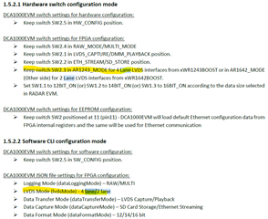
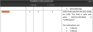
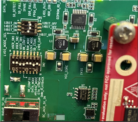
I am using AWR2243 coupled with DCA1000. I am trying to translate my radar parameters from mmwave studio to mmwaveconfig.txt file, but having issues with the laneEn command. AWR2243 is a 4 lane device, so I believe the laneEn parameter needs to be set to 15 (I enable all 4 lanes in mmwave studio).
A 10 seconds of data I acquire from mmwave studio becomes 270 mb (10 sec*25 fps*88 chirp loops*3 chirps*256 adc samples*16 bits) which is correct, but when I record data using CLI and the attached mmwaveconfig file, the data becomes only 135 mb. When I set laneEn to 3 (2 transmitters in binary), the raw data becomes 270 mb, but this time half of the data is coming as all zeros. When I set laneEn to 4 (1 transmitter), this time data becomes above 300mb, but 3/4 of data becomes all zeros again. My questions are:
1 Is this the expected behavior of laneEn command?
2 Where can I get more detailed information about DFP doxygen parameters under C:\ti\mmwave_dfp_02_02_03_01\ti\control\mmwavelink\docs\doxygen\html\classes.html? They don't seem to have much explanation and some command names are inconsistent with the ones in mmwaveconfig.txt.
3 How should I modify my .txt file to have the same configuration as mmwave studio?

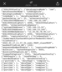
 I have post mmwaveconfig.txt below., Please check it and  give some suggestion ,thank you very much!

#
#For detailed view of mmWave Radar configuration structure
#please refer 
#ti\control\mmwavelink\docs\doxygen\html\index.html
#
#
#For detailed view of mmWave Radar configuration structure
#please refer 
#ti\control\mmwavelink\docs\doxygen\html\index.html
#

#
#Global configuration
#Advanced frame test enable/disable; 1 - Advanced frame; 0 - Legacy frame
#Continuous mode test enable/disable; 1 - Enable; 0 - Disable
#Dynamic chirp test enable/disable; 1 - Enable; 0 - Disable; This should not be enabled if Advanced chirp test is enabled
#Dynamic profile test enable/disable; 1 - Enable; 0 - Disable
#Advanced chirp test enable/disable; 1 - Enable; 0 - Disable; The legacy chirp API is not required if this is enabled
#Firmware download enable/disable; 1 - Enable; 0 - Disable
#mmWaveLink logging enable/disable; 1 - Enable; 0 - Disable
#Calibration enable/disable; To perform calibration store/restore; 1 - Enable; 0 - Disable
#Calibration Store/Restore; If CalibEnable = 1, then whether to store/restore; 1 - Store; 0 - Restore
#Transport mode; 1 - I2C; 0 - SPI
#Flash connected enable/disable; 1 - Enable; 0 - Disable
#
LinkAdvanceFrameTest=0;
LinkContModeTest=0;
LinkDynChirpTest=1;
LinkDynProfileTest=0;
LinkAdvChirpTest=0;
EnableFwDownload=1;
EnableMmwlLogging=0;
CalibEnable=0;
CalibStoreRestore=1;
TransferMode=0;
IsFlashConnected=1;
#END

#
#power on master arguments, please modify if needed.
#rlClientCbs_t: crcType 0:16Bit/1:32Bit/2:64Bit, ackTimeout
#
crcType=1;
ackTimeout=50000;
#END

## Custom for TDM
#waveformType = "legacyFrameChirp";
#MIMOScheme = "TDM";
#END

#
#channel config parameters, please modify if needed.
#rlChanCfg_t
#
channelTx=7;
channelRx=15;
cascading=0;
#END

#
#ADC out config parameters, please modify if needed.
#rlAdcOutCfg_t
#
adcBits=2;
adcFormat=1;
#END

#
#DATA format config parameters, please modify if needed.
#rlDevDataFmtCfg_t
#
rxChanEn=15;
adcBitsD=2;
adcFmt=1;
iqSwapSel=0;
chInterleave=0;
#END

#
#Low power config Paramters, please modify if needed.
#rlLowPowerModeCfg_t
#
anaCfg=0;
lpAdcMode=0;
#END


#
#Data Path config parameters, please modify if needed
#rlDevDataPathCfg_t
#
intfSel=1;
transferFmtPkt0=1;
transferFmtPkt1=0;
cqConfig=0;
cq0TransSize=0;
cq1TransSize=0;
cq2TransSize=0;
#END

#
#LVDS clock config parameters, please modify if needed
#rlDevDataPathClkCfg_t
#
laneClk=1;
dataRate=1;
#END

#
#SET HSI clock parameters, please modify if needed.
#rlDevHsiClk_t
#
hsiClk=9
#END

#
#LANE config parameters, please modify if needed.
#rlDevLaneEnable_t
#
laneEn=15;
#laneEn=3;
#END

#
#LVDS Lane Config parameters, please modify if needed.
#rlDevLvdsLaneCfg_t
#
laneFmtMap=0;
laneParamCfg=1;
#END


#
#Profile config parameters, please modify if needed.
#rlProfileCfg_t
#
profileId=0;
pfVcoSelect=0;
startFreqConst=1435384035;
idleTimeConst=10000;
adcStartTimeConst=500;
rampEndTime=5000;
txOutPowerBackoffCode=0;
txPhaseShifter=0;
freqSlopeConst=1655.03515;
txStartTime=0;
numAdcSamples=256;
digOutSampleRate=5688;
hpfCornerFreq1=0;
hpfCornerFreq2=0;
rxGain=48;
rfGainTarget=1,
#END

#
#Chirp #1 Configuration parameters, please modify if needed.
#rlChirpCfg_t
# txEnable = {b0 (ant0), b1 (ant1), b2 (ant2)}
# numOfChirpsToConfig = the number of defined chirp configs.
#
numOfChirpsToConfig=3;
chirpStartIdx=2;
chirpEndIdx=2;
profileIdCPCFG=0;
startFreqVar=0;
freqSlopeVar=0;
idleTimeVar=0;
adcStartTimeVar=0;
txEnable=2;

chirpStartIdx=0;
chirpEndIdx=0;
profileIdCPCFG=0;
startFreqVar=0;
freqSlopeVar=0;
idleTimeVar=0;
adcStartTimeVar=0;
txEnable=1;

chirpStartIdx=1;
chirpEndIdx=1;
profileIdCPCFG=0;
startFreqVar=0;
freqSlopeVar=0;
idleTimeVar=0;
adcStartTimeVar=0;
txEnable=4;

#END

#
#Frame configuration parameters, please modify if needed.
#rlFrameCfg_t
#
chirpStartIdxFCF=0;
chirpEndIdxFCF=2;
frameCount=0;
loopCount=88;
periodicity=8000000;
triggerDelay=0;
triggerSelect=1;
#END

# rlBpmChirpCfg_t
#chirpStartIdx = 1
#chirpEndIdx = 1
#constBpmVal = 48 # "0x30" in hex
#END


Best Regards,
Miao Bai
Texas Instruments Customer Support Center

  • Hi Miao,

    All these configurations from mmwaveconfig.txt is being configured to AWR2243 device using mmwavelink API from rlDeviceSetLaneConfig API.

    Document of mmwavelink APIs is available at <mmwave_dfp_02_02_03_01>\ti\control\mmwavelink\docs\doxygen\html\index.html

    Here I have linked the document which gives you mapping of LUA API (used by mmwave studio) to mmwavelink APIs (used in mmwavelink_example) to your better understanding, 

    /cfs-file/__key/communityserver-discussions-components-files/1023/Consolidated-LUA-and-mmWaveLink-API-Mapping-in-mmWaveStudio_2D00_v23_2D00_20220323_5F00_104018.pdf

    You need to change the lane for DCA1000EVM as well while capturing the data along with changing the lane selection from mmwavelink example. Above behaviour is due to mismatch of setting in DCA1000EVM and example application.

    Regards,

    Jitendra

  • Hi Jitendra,

        Thanks for your quickly response. I have asked the customer to check and reply you later.

        Thank you very much!

    Best regards,

    Miao Bai

  • Hi Jitendra,

       My customer still confused about how to change the lane for DCA1000EVM.

      Could you give detailed suggestion? Thank you very much!

    Best regards,

    Miao Bai

  • Hi Miao,

    Lane configuration needs to matched for AWR device as well as for DCA1000EVM.

    In above  mmwaveconfig.txt configuration file: laneEn=15;  means all four lanes are enabled for AWR device, i.e. ADC data will be streamed over all four lane of LVDS.

    Now same setting should be set with DCA100EVM

    To capture DCA1000EVM data you can optionally use command line tool available under mmwave Studio installation

    C:\ti\mmwave_studio_02_01_01_00\mmWaveStudio\PostProc  -  DCA1000EVM_CLI_Control.exe

    User guide for this exe is available C:\ti\mmwave_studio_02_01_01_00\mmWaveStudio\ReferenceCode\DCA1000\Docs\TI_DCA1000EVM_CLI_Software_UserGuide.pdf

    Search 'lane' in this document to find relevant information. And preferably go over full doc

    Regards,

    Jitendra

  • HI Jitendra,

        Thanks for your support.

        My customer is confused still because he configured the  like you suggested and the issue is not resolved.  

       Could you help to check the  cf.json  uploaded ?    The switch position and the lane parameter (lvdsMode) in the cf.json file looks correct. He don't know what else can be affecting this kind of behavior.

          Thank you very much!

    Best regards,

    Miao Bai

  • Hi Miao,

    Are they able to capture any valid data with DCA1000EVM (independent of lane selection)?

    Here are the DCA1000EVM deep switch setting for your reference.

  • Hi Jitendra,
        Thanks for your support.
        Regarding your suggestion,please check my customer's response:

        " As I mentioned, when I collect data with mmWave studio, the data is correct.
    I verified the results with both micro-Doppler spectrograms and Range-Angle maps by doing post-processing.
    In Jitendra's photos, it can be seen that his switch configuration is identical to mine, so I am not sure whether we are doing something else wrong or there is a software issue. If he has the setup he should be able to reproduce this issue I believe. "

        Could you kindly check it again? Thanks a lot.

    Best Regards
    Miao Bai
    TI Customer Support Center

  • Hi Miao,

    I need to try this at my end first to recreate their issue.

    I will get back here by Monday.

    Regards,

    Jitendra

  • Hi Jitendra,

         Greetings for the Day!    

         Is there any update about your test? 

        If you have any further suggestion, please share it to us, thank you very much!

    Best regards,

    Miao Bai

  • Hi Miao,

    Apologies for delayed response here due to some unexpected task came into my bucket.

    I will do this test and update by end of tomorrow.

    Regards,

    Jitendra

  • Hi Miao,

    I have tried to capture 2-lane option with DFP example and here are my observations

    1. [4 lanes] Tried first with default application c:\ti\mmwave_dfp_02_02_03_01\ti\example\mmWaveLink_SingleChip_Example  [change frame count frameCount=100;  in mmwaveconfig.txt  single change] and in parallel run c:\ti\mmwave_studio_03_00_00_14\mmWaveStudio\PostProc\DCA1000EVM_CLI_Control.exe tool to capture the LVDS data 

    Ran first these two commands :  DCA1000EVM_CLI_Control.exe fpga cf.json  and DCA1000EVM_CLI_Control.exe start_record cf.json in one command prompt.

    Then ran C:\ti\mmwave_dfp_02_02_03_01\ti\example\mmWaveLink_SingleChip_Example\mmwavelink_example.exe

    After this exe ran, it gave me 50MB adc_data.bin file at mmWaveStudio\PostProc\  directory

    2. [2 Lanes] Now changed laneEn=15;  to laneEn=3;  in mmwaveconfig.txt

    and  changed "lvdsMode": 2, in mmWaveStudio\PostProc\cf.json.

    Then follow the same steps as above which gave me same adc_data.bin file size (50MB).

    This proves that even with 2 lanes it captures the same size of adc data from AWR using DCA1000EVM.

    Please be noted that changing lane from 4 to 2 will reduce the number of lanes only but it streams the same size of ADC data over these 2 lanes now.

    Regards,

    Jitendra

  • Hi Jitendra,


        Thank you for your support. I have asked the customer to check and reply you later.
        Thank you very much!


    Best regards,
    Miao Bai

  • Hi Jitendra,

        Sorry for late response. 

        My customer have done some testing as you suggested, The data size being acquired is correct.

        But he have some confusion, please give some explain , thank you very much!

       " In the mmwave single chip example's mmwaveconfig.txt file they define 3 different chirp profiles and all of them has numadcsamples=256, but in the frame configuration part, they set numadcsamples=512. That's why the data size is being doubled and looks like correct, but the received data in these settings are being corrupt. Can you ask Jitendra why number of adc samples are being set to 512 in TI's example although they define all the chirps with numadcsamples=256? "

       Best regards,

       Miao Bai


  • Hi Miao,

    numadcsamples in profile config sets without consideration of real or complex ADC data type, so there is has set to 256.

    But in the frame Config API, numAdcSamples parameters is based on real/complex ADC data type. And in the example ADC data is set to complex type, so in the frame config it is set to double (256*2: I/Q type of complex ADC data).

    Here is the basic formula to calculate the ADC data size of each chirp:

    ChirpAdcSize = 256 (ADC sample size) * 2 (16 bits each sample) * 2 (if complex type) * 4 (number of Rx)

    For N frames captured ADC file size = (ChirpADcSize * N).

    Regards,

    Jitendra

  • Hi Jitendra,
        Greetings for the Day!
        Thank you very much for your patience and professional support.The customer has solved his problems.
        He is very satisfied with your support. Let me convey gratitude on his behalf.
        Thank you very much!

    Best Regards,
    Miao Bai