This thread has been locked.

If you have a related question, please click the "Ask a related question" button in the top right corner. The newly created question will be automatically linked to this question.

IWR6843AOPEVM: IWR6843AOPEVM

Part Number: IWR6843AOPEVM

Hello,

this request was previously started with CS0943460, but was redirected to by your colleagues.

part:

https://www.ti.com/lit/ds/symlink/iwr6843aop.pdf?ts=1647880550761&ref_url=https%253A%252F%252Fwww.ti.com%252Fproduct%252FIWR6843AOP%253Futm_source%253Dgoogle%2526utm_medium%253Dcpc%2526utm_campaign%253Dti-null-null-xref-cpc-pf-google-wwe%2526utm_content%253Dxref%2526ds_k%253DBGT60LTR11AIP%2526dcm%253Dyes%2526gclid%253DCjwKCAjwxOCRBhA8EiwA0X8hi4_fZuZSOJRMlp2Q2FGm-dADvjYLG5A6VvuFUkJ3Fe7FRVojR_bnJxoCHecQAvD_BwE%2526gclsrc%253Daw.ds


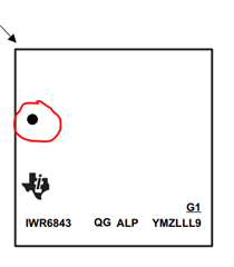
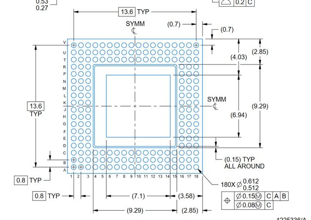
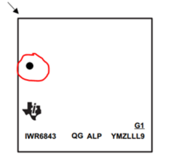
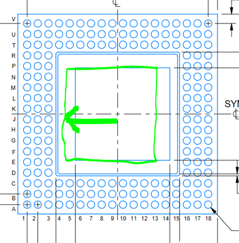
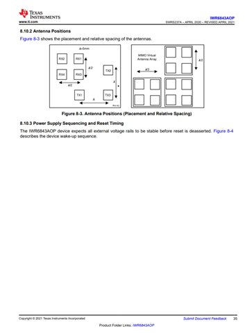
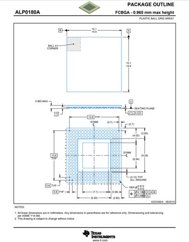
there is a problem defining pin A1. I find a definition on page 35 and on page 79 too.

The two definitions contradict each other.

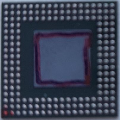
For the definition on page 79, we considered that the thermal pad is not symmetrical.

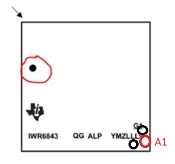
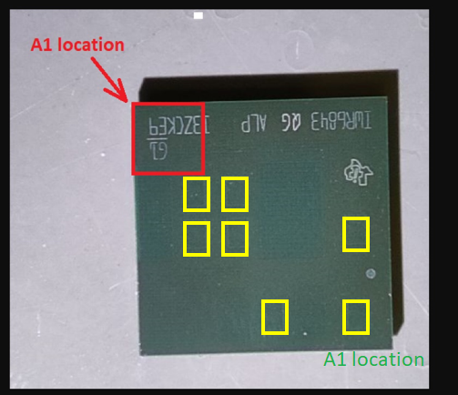
As defined on page 79, A1 is in the red marked on "Part image"

As defined on page 35, A1 is in the green marked on "Part image"


Please help me !

Zoltan Suto


  • Hi Zoltan, 

    The images on Page 35 and 79 are relative to the position of Pin A1.

    The image on Page 35 is just a 180 degree rotated version of the figure on page 79 OR you could say vice versa as well. 

    In order to find the position of A1 on the device, just follow the position of the black dot : 

    For example, in the snip above, corresponding to the circled black dot, the position of the pin A1 is top-left as highlighted by the arrow. 

    Based on the pin A1 placement, you can now figure out the antenna position. 

    Hope that clears your concern. 

    Regards,

    Ishita

  • Hello Ishita,

    i will show the problem again.

    This is the Part drawing from below. I design the PCB according this drawing. A1 is at the bottom left.

    A1 is positioned by the asymmetric thermal pad.

    This is the same only on the physical part. A1 is at the bottom left.

    I'll turn the part over. The A1 foot marked in red in Figure 2 will be in the lower right corner of Figure 3. So not according to your designation. If the assembly company identifies the part according to your marking (dot at top left), it will rotate the part 180 degrees.

    Unfortunately, this has happened !!!

    What do you think?

    Zoltan Suto

  • Hello Zoltan, 

    Let me check this with the team internally and I shall get back to you with my insights. 

    Regards,

    Ishita

  • Hello Ishita,

    thank you for your further efforts.

    My further comment:


    If the dot on part top is the marker A1 page 35,
    then there is an error the mechanical drawing on page 79 .
    The thermal PAD should be shifted in the other direction. Green arrow.
    This will solve everything.


    Best Regards,

    Zoltan

  • Hi Zoltan, 

    Looks like your concern might prove to be right. I'm still discussing this internally with the team and trying to get a final confirmation on it. 

    Will keep you posted on the developments. 

    Thankyou for your patience. 

    Regards,

    Ishita

  • Hello Ishita,

    the problem is still open.

    Regards,

    Zoltan

  • Hello Ishita,

    the problem is still open.

    Regards,

    Zoltan

  • Hello Zoltan, 

    Apologies for the delay on this as I was out of office last week. 

    Yes, you were right, Asymmetry of the die position makes correct A1 position to be on the bottom right as opposed to top left as shown in the current datasheets. 

    We have taken an action to correct this in the device datasheet. 

    I would like to take this opportunity to Thank You for bringing this very important piece of information to our notice. 

    Thanks & Best Regards,

    Ishita

  • Thank you Ishita,

    I will follow the change in the Datasheet..

    Zoltan