


Other Parts Discussed in Thread: AMC6821
Hi Team,
Good day! I'm posting this in behalf of the customer.
Here it is:
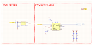
I'm using the AMC6821 to generate a PWM output to drive a fan, but I'm not using any of the interrupt or tach pins on the chip. I've attached the circuit and how I've wired up all the pins in the circuit.png attachment I've added. A Teensy 4.1 is controlling the chip.
Basically, All the pins are floating except the PWM-Mode tied to GND, A0 and A1 can either be tied to GND or V++ via a 0-ohm resistor, TACH input is left floating, and the PWM-out is routed to a high-frequency CMOS amplifier, I2C connected to the I2C line, and Vdd and GND tied to 3.3V and GND.
Code-wise, first I request the device ID from the 0x3D register, then it returns 0x21, so I know the I2C communication is working. Then I write to the Configuration 1 register the value 0x00 which should disable all interrupts and set the chip into Software DCY mode. Then I write to the Configuration 2 register the value 0x03, which should disable all the interrupts in the register, disable the TACH reading, disable the TACH correction circuitry, and enable the PWM output. Next, I write to the Characteristics register the value 0x1D (the default value), which should set the fan to 25kHz, spin up time of 2 seconds, and fan spin up enable. I then go on to toggle the Duty Cycle register between 0 and 255 every 5 seconds, which should give enough time for the fan to spin up to max speed. I've also attached the code we're trying to work with, it's just a really basic proof of concept using an Arduino framework to try and verify the functionality of the chip.
The problem I'm seeing is that the fan is not responding to the PWM output, and when the PWM output pin is probed with a Salae digital logic analyzer, the PWM signal is not seen. Is there anything I'm missing in terms of needing to write to other registers to just enable software DCY mode? I'm hoping I can find a software solution to this problem. I've also experienced some weirdness in terms of writing to Configuration Registers 3 and 4, especially because Configuration Register 4 has a "required configure bit" that I haven't seen any open source libraries using the chip utilize. Whenever I attempt to write to all 4 registers, I can only write to 1 register per upload to the board (i.e. upload code with config 1 to board, change to config 2, upload config 2, etc), or else the configurations being read in will go back to their default values. Is there a special protocol for writing to multiple registers that I'm missing?
Best regards,
Jonathan
