This thread has been locked.

If you have a related question, please click the "Ask a related question" button in the top right corner. The newly created question will be automatically linked to this question.

IWR6843AOPEVM: 3D People Counting - numADCSamples limitation

Part Number: IWR6843AOPEVM
Other Parts Discussed in Thread: IWR6843AOP, DCA1000EVM, MMWAVEICBOOST

Hi,

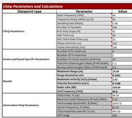
Our company wants to optimize the detection resolution (range, angular and elevation) based on a known maximum range and a minimum velocity resolution. We've had experience in the past with tuning the configuration, but we have an inquiry about the ADC sampling value with the 3D People Counting firmware v 4.7 - v 4.10.1

References:
Hardware -- IWR6843AOP EVM
[1] 3D_people_counting_detection_layer_tuning_guide.pdf (toolbox v 4.10.1)
[2] 3D_people_counting_tracker_layer_tuning_guide.pdf (toolbox v 4.10.1)
[3] Sensing Estimator (dev.ti.com/.../)
[4] Chirp Programming (www.ti.com/.../swra553a.pdf)
[5] 3D_people_counting_demo_implementation.pdf (toolbox v 4.10.1)


Question: With the firmware 3D People Counting v 4.7 - v 4.10.1, is it possible to have a numAdcSamples value higher than 128 (129+) ? If so, how can we achieve it ?

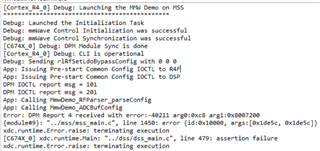
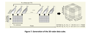
To respect the radar cube size of the default configuration set to 576KiB we tried to increase the number of ADC samples to 256 which would lead to a number of FFT bins of 256 as well. We there for reduces the number of chirp loops from 96 to 48 giving a radar cube size of (256 * 48 * 12 * 4) / 1024 = 576KiB. To accommodate the extra samples we increased the digoutsamplerate value from 2950 to 5900. Although this configuration should work the radar refuses to send values. we tried lowering the number of loops even further to 16 as well as increasing the sampling rate but the result is the same. Is there a hard limit on the number of ADC samples/ FFT bins in this version of the firmware, and if so how could we by pass it ?

Thank you for your kind support,
Justin

  • HI, Justin:

    Please go through the following thread to understand the chirp design and its limitation.   https://e2e.ti.com/support/sensors-group/sensors/f/sensors-forum/1011679/iwr6843aop-how-to-proceed-in-designing-testing-chirps

    For your specific question, you can use excel sheet provided in the above link to see what can go wrong with it.  In general, your approach should be fine, that you double the ADC rate and double the numADCsampels, which should then lead to the same ramp time and same RF bandwidth.   But do check with the excel sheet, and please lists the configuration before and after here. 

    If the excel sheet shows no error signs.   Then I am not sure whether the limitation can come with some internal memory issue with the people counting demo.  But let us first confirm that it is a valid configuration to the radar device.  Then we can continue on the demo related debug.  For example, you can run on the CCS environment and show us the any error message you have seen.

    Best,

    Zigang

  • Hi Zigang,

    Here's a valid configuration from where we can start:

    "dfeDataOutputMode" : "1",
    "channelCfg" : "15 7 0",
    "adcCfg" : "2 1",
    "adcbufCfg" : "-1 0 1 1 1",
    "lowPower" : "0 0",
    "profileCfg" : "0 60.00 30.00 25.00 125.00 657930 0 32.0 1 128 2845.0 2 1 36",
    "chirpCfg0" : "0 0 0 0 0 0 0 1",
    "chirpCfg1" : "1 1 0 0 0 0 0 2",
    "chirpCfg2" : "2 2 0 0 0 0 0 4",
    "frameCfg" : "0 2 42 0 100 1 0",
    "dynamicRACfarCfg" : "-1 4 4 2 2 8 12 4 8 4.00 6.00 0.40 1 1",
    "staticRACfarCfg" : "-1 6 2 2 2 8 8 6 4 8.00 15.00 0.30 0 0",
    "dynamicRangeAngleCfg" : "-1 1.00 0.0010 1 0",
    "dynamic2DAngleCfg" : "-1 3 0.0300 1 0 1 0.30 0.85 8.00",
    "staticRangeAngleCfg" : "-1 0 8 8",
    "antGeometry0" : "-1 -1 0 0 -3 -3 -2 -2 -1 -1 0 0",
    "antGeometry1" : "-1 0 -1 0 -3 -2 -3 -2 -3 -2 -3 -2",
    "antPhaseRot" : "1 -1 1 -1 1 -1 1 -1 1 -1 1 -1",
    "fovCfg" : "-1 50.0 20.0",
    "compRangeBiasAndRxChanPhase" : "0 1 0 1 0 1 0 1 0 1 0 1 0 1 0 1 0 1 0 1 0 1 0 1 0",
    "staticBoundaryBox" : "-1.2 3.3 0.1 12 -1.6 1",
    "boundaryBox" : "-1.2 3.3 0.1 12 -1.6 1",
    "gatingParam" : "3 2 2 3 4",
    "stateParam" : "3 3 6 50 25 6000",
    "allocationParam" : "100 200 0.1 20 0.5 20",
    "maxAcceleration" : "0.3 0.3 0.3",
    "trackingCfg" : "1 2 800 4 46 96 100",
    "presenceBoundaryBox" : "-4 4 0.5 6 0 3",
    "sensorPosition" : "0 0 0",


    The excel sheet doesn't show any error and the IWR6843AOP accepts this configuration. The radar cube size should be: (128 * 42 * 12 * 4) / 1024 = 252 KiB
    Now, doubling the digOutSampleRate value should indicate if there would be an error related to the sampling speed or computation time:

    "profileCfg" : "0 60.00 30.00 25.00 125.00 657930 0 32.0 1 128 5690.0 2 1 36"

    This configuration is also valid and works with the IWR6843AOP People counting demo. The radar cube size hasn't changed

    Since we've doubled the digOutSampleRatewe should be able to double the numADCsamples (128 -> 256) without impacting the valid Bandwitdh sweep, only increasing the radar cube size to: (256 * 42 * 12 * 4) / 1024 = 504 KiB, which is still less than the original cube size for the people counting lab

    "profileCfg" : "0 60.00 30.00 25.00 125.00 657930 0 32.0 1 256 5690.0 2 1 36"

    This time, the configuration is systematically rejected by the device. Please advice

    With [5], we've tried to see if we were infringing any memory limitation within the heap memories. We can see that for the DSS, the L3 heap memory allocation is set to 132 KB (does not include the radar cube) [5][7.1.1] and that it is impacted by the rangeFFTsize [5][7.3]. However, the relation remains unclear and incomputable


    Thank you again for your time,

    Justin

  • Justin,

    I agree that theoretically this should be a do-able configuration. I calculated the following values using your chirp profile. 

    Can you please share the exact error message you get when you set the profile cfg to profileCfg" : "0 60.00 30.00 25.00 125.00 657930 0 32.0 1 256 5690.0 2 1 36"

    Thank you,

    Angie

  • Hi Angie,

    Unfortunately, as I don't have the DCA1000EVM right now, I cannot stream the onboard messages except for the standard ones from the data com port

    Justin

  • Hi Justin,

    Do you have an MMWAVEICBOOST or are you running this in standalone mode?

    Thanks,

    Angie

  • Hi Angie,

    Our company doesn't hold any MMWAVEICBOOST either - we run in standalone and communicate over UART

    Thanks,
    Justin

  • Hi Justin,

    For debuging in CCS I would highly recommend an MMWAVEICBOOST. This will let you use CCS debug and you will get clearer errors.

    For now, I will get back to you in 2 days with more information on what could be causing this error. 

    Thank you,

    Angie

  • Hi Justin,

    I just sent your config with my MMWAVEICBOOST attached in ccsdebug mode and received the following error: 

    [C674X_0] xdc.runtime.Main: "../dss/dss_main.c", line 479: assertion failure
    xdc.runtime.Error.raise: terminating execution

    This is a runtime error being caused by a DPM error with code -40211. Here is a thread which details how to read these error codes: https://e2e.ti.com/support/sensors-group/sensors/f/sensors-forum/922019/awr1843-dpm-error-causing-runtime-to-crash 

    Thank you,

    Angie

  • Hi Angie,

    Looking up at the error code, the people_counting lab gives back the following error label:


    /** * @brief Error Code:
    Out of L3 RAM during detection matrix allocation. */ #define DPC_OBJDETRANGEHWA_ENOMEM__L3_RAM_DET_MATRIX (DP_ERRNO_OBJDETRANGEHWA_BASE-12)

    In my first post of this thread, I mentioned the possibility of running out of L3 memory as increasing the numADCsamples to 129 + also increases the rangeFFTsize from 128 to 256 Kb (as per [5]). The error message now confirms it, but the computation remains unclear.

    Since we now know the numADCSamples limitation, I can resolve this issue. Thank you for your time

    Justin