This thread has been locked.

If you have a related question, please click the "Ask a related question" button in the top right corner. The newly created question will be automatically linked to this question.

AMC6821: Nonsensical values from local temperature sensor.

Part Number: AMC6821

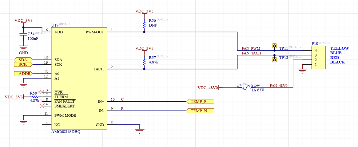
Reading the local temperature sensor on the AMC6821 gives around 80-90C.  This is immediately after power on, so the AMC6821 should be basically at room temperature, and using a thermal camera shows the AMC6821 is indeed around room temperature.

Also, the value jumps around a lot - perhaps 8 degrees between two readings a second or so apart.  

All other reads and writes to the AMC6821 have the expected results.

Are there any software settings that could possibly cause this behavior?  The configuration registers are set as shown below:

/* Fan configuration registers*/
// Default:       11010100
#define CONFIG1	0b01101001
//                ||||||||
//				  |||||||\- START (Enables temperature and speed monitoring)
//				  ||||||\-- INT-EN (Enables interrupt from n_SMBALERT pin)
//				  |||||\--- FANIE (Fan RPM interrupt enable)
//				  ||||\---- PWMINV (0: active low PWM.  1: active high PWM)
//				  |||\----- FAN-Fault-EN (Enables n_FAN-FAULT output)
//				  |\\------ FDRC[0:1] (00: DCY ctrl. 01: RPM ctrl. 10: remote temp ctrl. 11: local/remote temp ctrl)
//				  \-------- THERMOVIE (Enables THERM interrupt)

// Default:       00111101
#define CONFIG2	0b00000111
//                ||||||||
//				  |||||||\- PWM-EN (Enables pwm output)
//				  ||||||\-- TACH-MODE (0: For fans where power is PWM'd. 1: For fans where power is constant and PWM is a control signal)
//				  |||||\--- TACH-EN (Enable TACH)
//				  ||||\---- RTFIE (Remote temp sensor failure interrupt enable)
//				  |||\----- LTOIE (Local temperature interrupt enable bit)
//				  ||\------ RTOIE (Remote temperature interrupt enable bit)
//                |\------- PSVIE (LPSV interrupt enable)
//				  \-------- RST (Write 1 to reset device)

// Default:       10000010
#define CONFIG3	0b10000010
//                ||||||||
//				  ||||\\\\- Part rev number (Read only, read back 0010)
//                |\\\----- Reserved (Read only)
//				  \-------- THERM-FAN-EN (Forces fan to 100% DCY under overtemp conditions)

// Default:       00001000
#define CONFIG4	0b10001000
//                ||||||||
//				  ||||\\\\- Reserved (Read back 1000)
//				  |||\----- OVREN (Enable n_OVR pin)
//				  ||\------ TACH-FAST (0: Tach updates at 1Hz. 1: tach updates at 4Hz)
//                |\------- PSPR (Fan tach output pulses per revolution. 0: 2 PPR. 1: 4 PPR)
//				  \-------- MODE (Must write 1 to this bit)

// Default:       00011101
#define FANCHAR	0b00011101
//                ||||||||
//				  |||||\\\- STIME (Spin up time. [0.2, 0.4, 0.6, 0.8, 1, 2, 4, 8] seconds. 0b101 = 2 seconds.)
//				  ||\\\---- PWM (PWM frequency.  [1, 10, 20, 25, 30, 40, 40, 40] kHz.  0b011 = 25kHz))
//				  |\------- Reserved
//				  \-------- FSPD (0: Fan spin up enabled. 1: disabled.)

// Default:       01010010
#define DCYRAMP	0b10010010
//                ||||||||
//				  ||||||\\- THRE (Duty cycle change threshold.  Only used in temp control mode.)
//				  |||\\\--- RATE (Duty cycle update rate.  Ignored in RPM control mode - use TACH-FAST instead.)
//				  |\\------ STEP (Max DCY step size, out of 256. [1, 2, 4, 8] counts.)
//				  \-------- RAMPE (Ramp enable.  If disabled, new duty cycles take effect immediately.  Ignored (forced on) in rpm ctrl mode)

  • Hi Eric,

    Can you tell me the raw hex or binary value you are seeing in the temperature registers 0x06 and 0x0A?

    thanks,

    ren

  • Register 0x0A is jumping around a lot.  I did 10 reads half a second apart and got the following values:

    Reg 0x06 Reg 0x0A Reg 0x0A hex
    10100111 (Binary) 97 0x61 (Hex)
    10100111 (Binary) 97 0x61 (Hex)
    10000111 (Binary) 102 0x66 (Hex)
    11100111 (Binary) 86 0x56 (Hex)
    10000111 (Binary) 90 0x5a (Hex)
    00100111 (Binary) 97 0x61 (Hex)
    11000111 (Binary) 85 0x55 (Hex)
    11000111 (Binary) 93 0x5d (Hex)
    01100111 (Binary) 97 0x61 (Hex)
    11000111 (Binary) 88 0x58 (Hex)

    Reg 0x0B is always returning 127, but that may be because my remote temp sensor isn't wired correctly, I haven't been able to validate that yet.

  • Hi Eric,

    Can you please double check that you're not doing any post processing of the Reg 0x0A values shown? Your output would be a sensible 25C output if it were right shifted by 2. Alternatively, have a look at the I2C transactions with a scope or logic analyzer.

    Can you share your schematic?

    thanks,

    ren

  • Below is a logic analyzer capture of the I2C traffic.  The register values match what I'm seeing in software.

    SampleNumber I2C
    120104 S
    120199 W:18h
    121021 A
    121124 06h
    121946 A
    122102 P
    122218 S
    122313 R:18h
    123134 A
    123237 87h
    124059 N
    124214 P
    124313 S
    124408 W:18h
    125230 A
    125333 0Ah
    126155 A
    126311 P
    126435 S
    126530 R:18h
    127352 A
    127455 61h
    128276 A
    128379 7Fh
    129200 N
    129356 P
    129445 S
    129541 W:18h
    130363 A
    130466 00h
    131288 A
    131444 P
    131564 S
    131659 R:18h
    132481 A
    132584 29h
    133406 N
    133562 P
    133689 S
    133784 W:19h
    134606 A
    134709 06h
    135531 A
    135687 P
    135813 S
    135909 R:19h
    136730 A
    136833 07h
    137654 N
    137810 P
    137900 S
    137995 W:19h
    138817 A
    138919 0Ah
    139742 A
    139898 P
    140022 S
    140117 R:19h
    140938 A
    141041 5Fh
    141863 A
    141966 7Fh
    142788 N
    142945 P
    143047 S
    143142 W:19h
    143964 A
    144067 00h
    144889 A
    145046 P
    145167 S
    145262 R:19h
    146084 A
    146186 29h
    147008 N
    147164 P
    147406 S
    147501 W:19h
    148322 A
    148425 08h
    149247 A
    149403 P
    149519 S
    149614 R:19h
    150435 A
    150538 FFh
    151359 A
    151461 FFh
    152282 N
    152439 P
    152555 S
    152650 W:19h
    153472 A
    153575 22h
    154396 A
    154553 P
    154673 S
    154768 R:19h
    155590 A
    155692 FFh
    156513 N
    156670 P
  • Eric - 

    What is ADDR connected to? can you whole schematic and also include your pullup resistors? is there more than one AMC6821 connected?

    is there a reason you do not populate your R56, but you did populate R57?

  • There's not much to the rest of the schematic.  ADDR is tied either high or low to address the two AMC6821s.  Inside the left block, the I2C just connects to an STM32 microcontroller's I2C port, with two 4.7k pull-ups to 3.3V.  I'm confident the I2C is working correctly since I can read and write all the other registers and get the expected behavior.

    I DNP'd R56 because the fan we're using (QFR1248GHE-SP01) has an internal pull-up, and populated R57 because the fan tach output is open collector. 

  • Eric,

    I'm inclined to believe something is making your AMC6821 hot, and you're just not able to see it with your thermal camera. We're not seeing anything to cause it in your schematic (although maybe there is some 48V path through your fan, whether continuous or transient.) There may still be corruption in the bus result that your logic analyzer is hiding, but it seems unlikely. 

    Failing all that, we'd have to call your device(s) faulty and ask for you to return them. How many devices have you observed this on? If all of your devices do it, it's more likely to be a system problem that we're simply not seeing.

    thanks,

    ren