Other Parts Discussed in Thread: TDA2, AWR2243, MMWCAS-DSP-EVM, , AWR1243
Hello experts
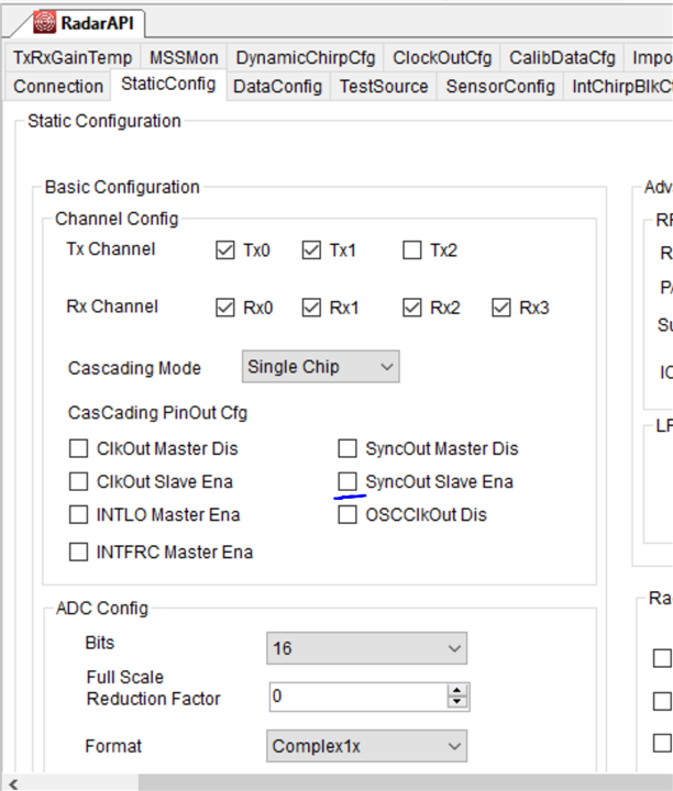
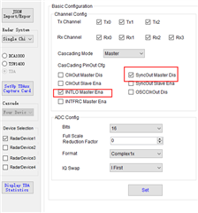
We currently want to do the test and verification of the RF board and the data acquisition and analysis of the whole board based on two AWR2243 cascaded + TDA2. Currently, the relevant firmware and parameter configuration can be downloaded normally through the mmWave studio and data collection can be done, the master chip is normal, but the slave chip seems to work abnormally. When the target exists, the master chip channel has obvious target peak, but the slave chip cannot see the target peak, as if there is no normal signal transmission and reception;
master:
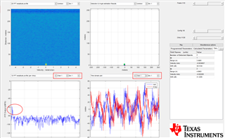
Slave:
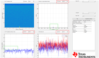
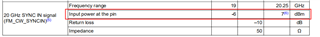
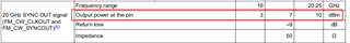
We suspect that the slave chip is abnormal due to the lack of FM_CW_SYNCIN signal (and SYNC_IN) input from the slave chip, resulting in no signal transmission and reception in the transceiver channel. We want to verify it through the Monitoring Report based on MMWCAS-RF-EVM+MMWCAS-DSP-EVM.
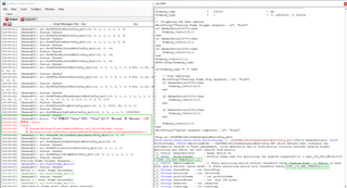
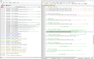
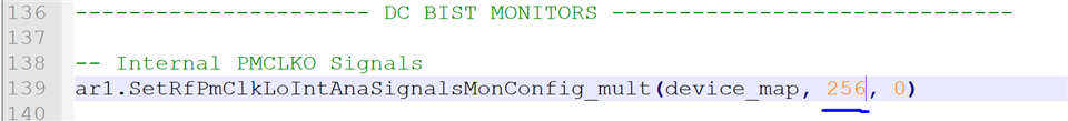
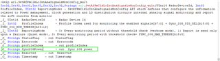
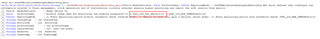
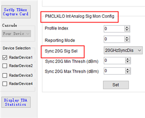
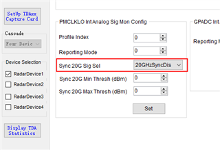
Currently, I want to read the LO signal power value (IntPMCLKLOAnalogSignalMonitoring) of the master-slave chip through ar1.SetRfPmClkLoIntAnaSignalsMonConfig_mult(device_map, 256, 0) ——(mmwave_studio_03_00_00_14\mmWaveStudio\Scripts\Cascade\Cascade_Monitoring_Example.lua)to verify whether the slave chip has LO signal input, but the report read from Cascade_Monitoring_Example.lua shows that the power of the LO signal is not correct, all of which are 0, as shown in the figure below, why the API command configuration in Cascade_Monitoring_Example.lua is not correctly?How to modify the API command corresponding to the configuration? The command of this lua script is the same as that of DFP?What is the difference between the commands?
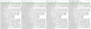
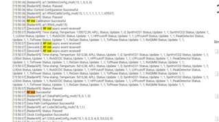
By the way, for ar1.SetRfPmClkLoIntAnaSignalsMonConfig_mult(device_map, 256, 0) command, when the second bit is set to 16/32, there will be an error in the console, modified it to 256 will not report an error, as shown in the figure below. How to set the value threshold here and how to modify it?
Thanks.