Because of the holidays, TI E2E™ design support forum responses will be delayed from Dec. 25 through Jan. 2. Thank you for your patience.

This thread has been locked.

If you have a related question, please click the "Ask a related question" button in the top right corner. The newly created question will be automatically linked to this question.

IWR6843AOP: AWR6843AOP

Part Number: IWR6843AOP
Other Parts Discussed in Thread: AWR6843AOP, UNIFLASH, AWR6843, AWR6843AOPEVM, MMWAVEICBOOST

I'm developing a board with the AWR6843AOP device from TI. To be sure that we are not going to have the big problems, I copied exactly the demo board of IWR6843AOP. I used the left part of the board which is advised by TI for utilization of Radar part.

With this new board I have a problem for flashing my micro-controller. the flashing is done by USB port and there is a bridge on the board for converting the USB signals to UART signals. Even by fixing S3 switch on 'ON' position, the micro-controller does not go to programming mode.

I tried to verify everything. The LED of bridge turns On when I connect my board to PC USB port. it stays ON for 10 seconds. on the PC interface I saw the below message
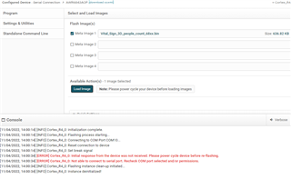
I checked the RX and TX on scope. their level is 3.3 volts but nothing moves on them.

The schematic of my board is int the follow link:

transfert.free.fr/neDqpH

I will appreciate if anybody can help me to solve my problem

Thank you

Bijan

  • Hi Bijan,

    Can you confirm you have successfully flashed and ran the Out of Box Demo on both the TI EVM and your developed board?  We usually advise this before moving on to more complex demos.

    Regards,

    Brennan

  • Hi Brennan,

    I am the FAE supporting this customer. Their issue is not an environment issue as on the same PC, they can successfully flash and run TI firmware. They say that they have cloned our IWR6843AOP EVM (to which they have added more devices required by their application), but when they try to flash the radar firmware, Uniflash reports the above issue.

    So that's more likely a hardware issue. You may access here (TI internal link) their schematic. It would be good that someone reviews what specifically linked to flash programming. I have reviewed SOP0/1/2 and a few things, but I did not find what could cause the problem. I did see that the IWR6843AOP JTAG signals are left unconnected, but from other posts on the forum, this does not seem to be an issue that could block the device and making it unresponsive.

    Thank you.


    Best regards,
    François.

  • Thank yo Brennan for your reply

    we use daily the TI EVM. On two TI parts we had some difficulties to flash. but generally speaking I have no problem for flashing TI EVM. Sure I have to respect the order of operation. but never the problem with my TI EVM. My colleague working on the software makes run the EVM without any problem neither.

    Bijan

  • Hello,

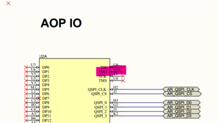
        For the boot-mode configuration (Functional mode, Flashing mode or Debug mode) SOP lines need to be configured. 

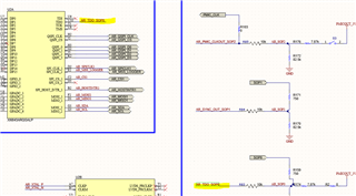
    In the current design TDO (This is one of the boot mode signal) is not connected to any signal as shown below. 

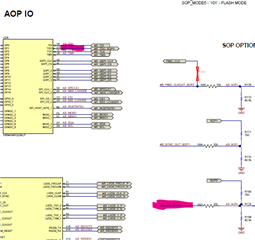
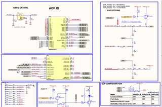
    Please refer to the below reference schematic for the SOP mode connection in the EVM.

    Without proper SOP assertion flashing mode or functional mode cannot be configured. 

    Thanks and regards,

    CHETHAN KUMAR Y.B.

  • Thank you very much Chethan.

    I will modify the layout. I hope this is the only problem

  • Bijan,

        Thanks for the confirmation. Yes, without the SOP assertion boot mode will not be recognizable by the device. Hence it's important to assert the boot mode for the device through the SOP lines. 

    Thanks and regards,

    CHETHAN KUMAR Y.B.

  • Hi CHETHAN;

    we applied the modification

    we still have the same problem. I fixed S3=1 but PC does not still recognize the com connection !!

    SOP0 and SOP1 are not connected any where as on the schematic (OFF)

    SOP2 which is S3 is connected to PMICOUT_3V3

    any idea where I'm making a mistake ?!

    Thank you for your help

    Bijan

  • Bijan,

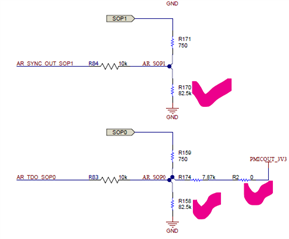
       SOP0 and SOP1 need to be connected and driven as below, they define the BOOT Mode for the device. NO connections will not define the bootmode for the device.  

    Below are the boot modes of the device: 

    Also during the boot operation do not connect any external interface (external cable, I/Os driving from external entity). It would mess up the boot modes. 

    For hardware setup you could refer to the below training material and video links.

    https://dev.ti.com/tirex/explore/node?node=AMLjV2I4hAEEwpYRfP2okA__VLyFKFf__LATEST

    https://training.ti.com/hardware-setup-iwr6843aop

    Thanks and regards,

    CHETHAN KUMAR Y.B.

  • Hi Bijan,

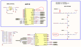
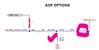
       Also please ensure that below R103 is not connected, it would affects the boot mode. 

    Thanks and regards,

    CHETHAN KUMAR Y.B.

  • Hi CHETHAN;

    So sorry to bother you so much. But there are two remarks;

    1- According to the schematic of Radar:

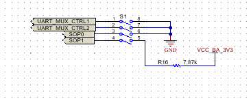
    If SOP0= S1.3 is in OFF, that means SOP0 is connected to nothing, same for SOP1. Another reason is when one breaks the TI demo board, the dip switch S1 does not exist anymore for controlling SOP0, and logically one can be able to flash the micro just by controlling SOP2(S3).

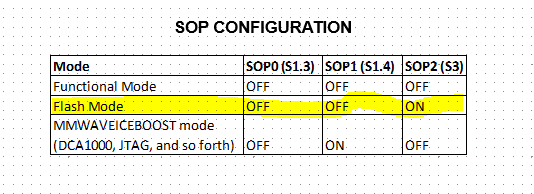
    2- You have the below table for flashing in your schematic :

    while you have another table on the same schematic which is

    for flashing the two conditions (yellow) in the two table are not the same!! In the first table SOP0(S1.3) has to be OFF. In the second table  SOP0 has to be 1! I think this is contradictory or I understand badly. Please advise me

    Thank you so much to help us to solve this issue

    Best regards

    Bijan

  • Hi CHETHAN:

    We are going to modify again our layout. the below page will be used for flashing the micro. please tell us if there is anything wrong on the schematic with respect to flashing.

    Thank you et best regards

    Bijan

  • Hi CHETHAN;

    Once we use the component AWR6843 on our board for the first time, we suppose that there is no boot loader and nothing programmed inside it. In this case can we flash the memory with the same procedure defined in 'hardware-setup' video?

    The problem is when we establish the connection as described in below photo

    The voltage at one side of R83 is about 3.3 volts and at the other side it is 0.5 volts. it seems that the port TDO is not well configured for output. maybe that's coming because there is no initial program inside AWR6843 for starting.

    So sorry for all these questions, Programming this device when it is not on demo board is really a Chinese puzzle

    thanks

    Bijan

  • Bijan,

         Both the configurations are correct, One is the switch position of  (SOP0 : S1.3, SOP1: S1.4, SOP2: S3) and another is definition of the actual SOP pins. Apologies if it's not clear from the previous posts.  

    When the switches are in off position pull up and pull down resistors defines the SOP values. This is even applicable when the board is board is broken into mission side alone, pull up and pull down resistors would be still connected and defines the SOP mode. In this condition one can exercise only flashing or functional mode, cannot enter in to debug mode in this condition.

    Below configuration shows SOP pull up and pull down condition when switches are in off state. 

    For example in flashing mode: switch positions (S1.3, S1.4 and S3) are off, off, on.  SOP0 (S3) will be pulled high through the external strong pull up. 

    PMIC_CLK (R103) must be removed, otherwise it will interfere on the bootmode. 

    Thanks and regards,

    CHETHAN KUMAR Y.B.

  • Hi CHETHAN;

    the problem of flashing mode of AWR6843 becomes really catastrophic for us!

    we established the connection between TDO and AR_TDO_SOP0. And I measure the voltage on different SOPs

    1- AR_PMIC_CLICKOUT_SOP2=1

    2 - AR_SYNC_OUT_SOP1=0

    3 - AR_TDO_SOP0=1

    4 - R103 removed

    But still AWR6843 does not want to go to flash mode.

    I would appreciate if you help us to get out this problem

    Bijan

  • Bijan,

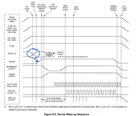
         For entering into flashing mode below power up sequence need to be ensured. 

    Most importantly, After SOP lines are asserted nreset need to be released. So that rising edge of NRESET release latches the status of the boot mode, And hence device enters into right boot mode, in this case flashing mode. 

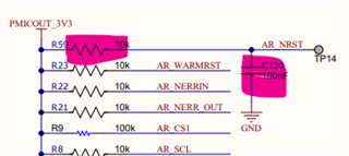
    It could be possible that for short time constant on the NRST line, NRESET release could be happening prior to SOP lines are in flashing mode state during the power up.   

    Perhaps, you could keep the NRESET low till the SOP lines are in the expected (101) state and release after SOP lines are stable. Alternatively you could change the RC time constant (Say 50-100msec depending upon power and SOP lines settling) on NREST line such that it will release supply/SOP lines are stable. Later you could optimize this time constant based on your system requirement. 

    Thanks and regards,

    CHETHAN KUMAR Y.B.

  • Dear CHETHAN,

    thank you so much following our problem.

    I did do the reset many times after connection to USB Port of my PC. still nothing!

    I have two AWR6843AOPEVM red board. One of them can be flashed easily. The second one has the same behavior as our board. It can't be flashed though all the conditions of flashing are present. That makes me think of: is the component (AWR6843) is dead? the oscillator runs. But the oscillator can run even if the component is dead.

    Can we use the JTAG pins for solving this problem. Is there any IDE running with JTAG pins?

    Thank you for your help

    Bijan

  • Bijan,

        Could check if there is NERROR is asserted or not in the system. If NERROR is asserted it would indicate some hardware fault in the system that need to be rectified. 

    I'm assuming that you have used the same flash part number as that of AWR6843AOPEVM, Otherwise there could be some problem.

    Yes, we could use the JTAG to check if the device is entering into flash mode or not. 

    We could use the below JTAG debugger 

    https://www.ti.com/tool/TMDSEMU110-U

    Please note external JTAG emulators must be removed during the power up and boot mode of operation, Otherwise it would interfere with the boot modes.

    If the device is not in the right SOP mode (device has not registered the SOP mode then) it may not connect UART port RX/TX into PC.

    This may need CCS connection to debug further. After connecting the JTAG into mmWave device you could:

    1. Read the SOP register and confirm if it is latching to the right value?

    SOP mode register: FFFF E268 (Flash mode should read 0x00000005, Functional Mode should read 0x00000001)

    1. Also read CR4CTL register (0xFFFFFF20), it should be 0x00ADAD00 for a successful boot and 0x00000000 for a boot failure. 

    If you have mmWaveICBoost board that has XDS110 integrated in it. you could connect the AWR6843AOPEVM and debug above points. If the AWR6843 is not working we could identify from the above tests. 

    Thanks and regards,

    CHETHAN KUMAR Y.B.

  • Dear CHETHAN ;

    Good News;

    I changed the PC and I can flash the device now.

    I don't understand why flashing AWR6843AOP depends on PC. If ever you have some information on that I will be appreciate to let me know.

    Thank you again for following our problem

    Bijan

  • Bijan,

         Thanks for the confirmation. Some times there are python scripts running in background which will not get terminated upon unsuccessful attempts of flashing process, it would remain running in background even after termination of Uniflash application. Background running python script which are connected to UART port, blocks the fresh attempt to connect the port in the new session.  Hence if there are unsuccessful attempts of flashing process did take place, at that time it's good practice to check in the task manager to see if there are any Python scripts related to Uniflash are running and terminate those. 

    Glad you were able to flash the device. Best wishes for your future tests. 

    Thanks and regards,

    CHETHAN KUMAR Y.B.