This thread has been locked.

If you have a related question, please click the "Ask a related question" button in the top right corner. The newly created question will be automatically linked to this question.

OPT3101-SDK: Stuck while calibrating, and finding temp coeff.

Part Number: OPT3101-SDK
Other Parts Discussed in Thread: OPT3101

Calibration Problems for OPT3101


We are using a custom 1 channel opt3101 sensor , to calibrate it we have followed
The steps as mentioned in “OPT3101 SDK Users Guide”

The differences from the steps are ,we have customized settings for linux as our board using OPT3101 sensor has one, instead of MSP we are using ADB to push code into our device .

While calibrating the major issues I am facing are:-
Erratic temperature.
For testing purposes while creating configuration file we have set frames sampling rate in the configuration tool such that we get 1.95 frames per sec.

Also in definition.h , we have set time in seconds between data points to be 20s.

-> yet the result is not following as expected of 20 sec for 1 data ,1 data / 20 sec , it's very fast in IN_LAB_STEP_2 mode , for finding temperature coefficient.
Also temp is very erratic ,it's not varying linearly up or down, eg :- while cooling down, from 43 it might go to 44 for some time then -> 45 ->43 ->42 ->43 ->41 ->42 like that.
It's heating up and cooling down in an analog wave like fashion.


The ways we tried to debug this , tried using a multimeter as a temperature sensor and kept the node on chip and tried the test IN_LAB_STEP_2 again , for 0.1 “c variation get temp in chip Tmain as +-3”c variation, also when in multimeter temperature became stable ,yet in chip reading tmain was varying, this is causing error while plotting graph.

We are going to use a thermistor to get a more accurate temperature reading of the chip rather than a multimeter.

2.in IN_LAB_STEP_1
After adding the configuration file only 1 reference distance is being asked .
Our custom board is only using 1 channel tx0.
But still shouldn't it ask for 1 in HDR mode 0 and 1.
It's only asking for HDR mode 1.
We have modified the OPT3101Coefficients.cpp refdistanceinMM for TX0 in HDR and non HDR mode to 500+10 and 500+20,
As our lens focal length can only capture at least at 50 cm distance.

After checking the configuration file generated by the configuration tool, the data related to tx0 is only present.

3.Cross talk problem

While doing the IN_LAB_STEP_0 experiment to find the crosstalk, we are finding that in channel 1 and 3 some amplitude and other values are coming, while in Tx2 all values are 0.

The setup is such that the photodiode has a plastic cylindrical covering similar to cameras and the IR sensor has a metallic hollow cylindrical small covering .
The length of photodiode covering is longer compared to IR sensors.
Is it possible that IR are passing through these coverings and entering hannels to create crosstalk.


I have tried covering the IR sensor with a camera cap a bit larger than required, an aluminum foil, both are giving amplitude higher than 700 whereas we require only below 600.

I got the best result with a coin which covers fully and a bit of pressure ,giving a best result of below 200 else below 500 in the worst case scenario.

Since before each test IN_LAB_STEP_1 ,IN_LAB_STEP_2 etc , we are doing a crosstalk talk test. I wonder if this is causing any mishap in tests.
Also we have normal led lights in the room where we are testing ,and we are using a tungsten lamp while heating the chamber for testing in IN_LAB_STEP 2. Will they cause any mishaps?

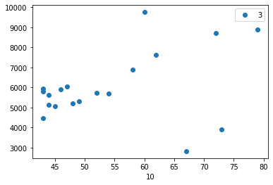
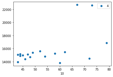
The major issue I got while plotting the graphs are for the same temperature and a wide range of I and Q values.
As there is a + or - 3’c difference , suppose for 35’c i will get values at 32’ to 38’c.

I would like to know more on what I and Q represent what does their polarity signify and can could my Electro static discharge from coin while covering with my hands effect these reading.

  • Hi Darsan,

    Regarding the HDR mode issue first, if you have configured properly for using HDR mode, you should have inputted the distances to calibrate at for each HDR setting and would have been asked to measure for HDR mode 0 and 1 during calibration. Recheck the configurator tool to make sure you have input your settings properly.

    The temperature of the chip could be related to how you have set up HDR mode so I would try this after fixing the first issue, but try reading the temperature at a faster rate so that you can obtain more details about when the temperature is changing and if it is related to the device switching currents. It looks to me like you were reading the temperature every 20 seconds.

    For crosstalk measurements, you should only be concerned about crosstalk for TX0 correct? So the values for TX2 should not matter. It is definitely possible that IR is passing through the coverings and entering the other channels, so I would recommend looking at 7.2 Optical Isolation section of the OPT3101 design doc. Also I would recommend using electrical tape to cover the IR sensor when measuring crosstalk (mentioned in OPT3101 SDK Users Guide). Finally, check the crosstalk without performing calibration so that you will be able to see the baseline crosstalk and how the calibration you are performing is reducing it.

    Thank you,

    Brent Elliott

  • Thanks Brent,

    we followed as you suggested, its a lot better now but still the issues haven't vanished .

    previously we hadn't selected the AUTO HDR mode, after selecting it i am getting all values 0 in Tx2 and Tx1 as expected.

    *In  IN_LAB_STEP_0:

    we are getting  amplitude value below 200 while using a coin as shield at ~ 180 , even without shielding i am getting nearly 210-220 only.

    I am wondering ,is there some error here.

    considering this amplitude value is measured as electrical and optical interference near photo diode, does IR optical interference only cause 20-30 deviation in amplitude. 

    *IN_LAB_STEP_1:

    everything working fine, asking 2 value of HDR 1 and 0 for Tx0.

    *IN_LAB_STEP_2:

    initially did photo diode shielding for cross talk elimination.then removed shielding.

    waited till ambient temperature reached nearly 50'c.

    then let the chip get stable for 2.5 mins.

    started taking reading.

    <- here is where we are stuck at.

    ERRATIC TEMPERATURE its not as worse as at the time of prev post, but still the data is garbage , and cannot move to the next stage.

    problems:-

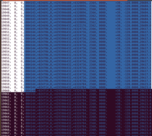
    1.the data is being taken at very rapid rate, nearly 1200 data in 1 min.(thus i am taking nearly 30000 reading to get variation in temp recorded)

    when temp increases from 38 to 39 it goes like 38 -> 39 ->38 ->38->39

    Count,TX ,HDR,      I,      Q,S, ScaledI, ScaledQ,tMain,tIlum,tMain(C),  tIlum(C),Magnitd

    10038, 0, 0,-004237,+026585,7,+4294424960,+3402880, 2400, 0000, +44, -128.0000,11077.6
    10038, 0, 1,-004237,+026585,7,+4294424960,+3402880, 2400, 0000, +44, -128.0000,11077.6
    10039, 0, 0,-004237,+026585,7,+4294424960,+3402880, 2400, 0000, +44, -128.0000,11077.6
    10039, 0, 1,-004237,+026585,7,+4294424960,+3402880, 2400, 0000, +44, -128.0000,11077.6
    10040, 0, 0,-004237,+026585,7,+4294424960,+3402880, 2400, 0000, +44, -128.0000,11077.6
    10040, 0, 1,-004237,+026585,7,+4294424960,+3402880, 2398, 0000, +43, -128.0000,11077.6
    10041, 0, 0,-004237,+026585,7,+4294424960,+3402880, 2400, 0000, +44, -128.0000,11077.6
    10041, 0, 1,-004237,+026585,7,+4294424960,+3402880, 2400, 0000, +44, -128.0000,11077.6
    10042, 0, 0,-004237,+026585,7,+4294424960,+3402880, 2400, 0000, +44, -128.0000,11077.6
    10042, 0, 1,-004237,+026585,7,+4294424960,+3402880, 2400, 0000, +44, -128.0000,11077.6
    10043, 0, 0,-004237,+026585,7,+4294424960,+3402880, 2400, 0000, +44, -128.0000,11077.6

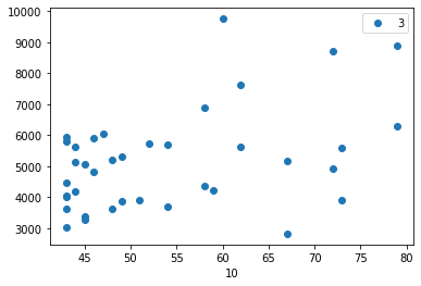
    also as in prev image it can be seen that same temperature is having different I and Q values varying.

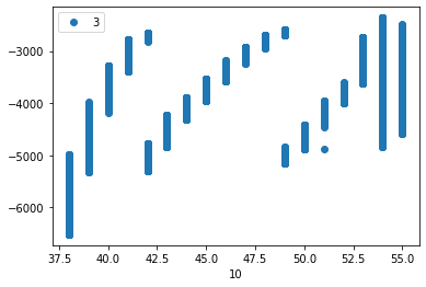
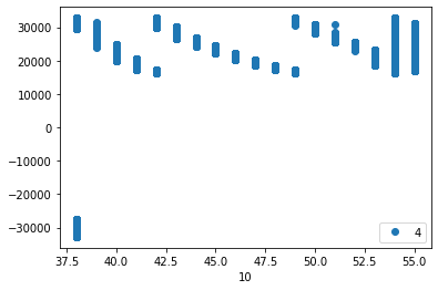
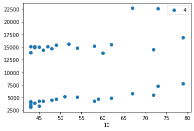
    also at same temperature i am getting a very big deviation in range for I and Q values.I have plotted the I,Q vs Temp graph .

    It can also be seen that instead of whats shown in "Figure 3. Illumination crosstalk coefficient determination" in "How to set up and calibrate OPT3101 based systems for proximity sensing" , we are getting opposite polarity for I and Q .

    then Q thus change abruptly in the end.

    25471, 0, 0,-005567,+032757,8,+4293542144,+8385792, 2352, 0000, +38, -128.0000,27344.9
    25471, 0, 1,-005567,+032757,8,+4293542144,+8385792, 2352, 0000, +38, -128.0000,27344.9
    25472, 0, 0,-005567,+032757,8,+4293542144,+8385792, 2352, 0000, +38, -128.0000,27344.9
    25472, 0, 1,-005568,+032763,8,+4293541888,+8387328, 2352, 0000, +38, -128.0000,27349.8
    25473, 0, 0,-005569,-032766,8,+4293541632,+4286579200, 2352, 0000, +38, -128.0000,27353.3
    25473, 0, 1,-005569,-032766,8,+4293541632,+4286579200, 2352, 0000, +38, -128.0000,27353.3
    25474, 0, 0,-005571,-032758,8,+4293541120,+4286581248, 2352, 0000, +38, -128.0000,27347.1
    25474, 0, 1,-005571,-032758,8,+4293541120,+4286581248, 2352, 0000, +38, -128.0000,27347.1
    25475, 0, 0,-005571,-032758,8,+4293541120,+4286581248, 2352, 0000, +38, -128.0000,27347.1

    The only difference we are doing are we have just changed SDK's settings for linux.

    the Points we would love to know are.

    1.What does I and Q represent.

    2.Whats their polarity representing.

    3. is there a way that our I and Q got interchanged , if yes ,where can i confirm in code.

    4. for solving rapid temperature to controllable rate what to do.

    we have changed definition.h

    #define TEMP_CYCLE_DELAY_IN_SECONDS_BETWEEN_DATA_POINTS 60 // to take 1 reading per min
    #define TEMP_CYCLE_TOTAL_NUMBER_OF_DATA_POINTS_PER_SETTING 65535// since above condition fails, as taking as many readings as needed to plot graphs.

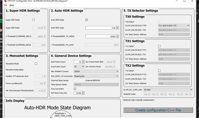
    the config file creation:

    Thank you for reading and helping.

  • Hi Darson,

    Wanted to give you a heads up that Brent is out of office rest of the week. We should be able to get you a response by early next week.

    Best,

    Alex

  • Hi Darsan,

    Please try using electrical tape to shield the PD as I am not sure what effect the coin could have with shielding. Also, can you directly share these images in the post instead of uploading to a file hosting website? I am looking at the other points that you brought up and would like to see the screenshots before going further.

    Thank you,

    Brent Elliott

  • image showing slight temperature variations at the edges ,eg 40->39 .

    I vs T

    Q vs T

    config file generation settings

  • Hi Darsan,

    I am looking into this and will get back to you shortly.

    Thank you,

    Brent Elliott

  • Hi Darsan,

    Have you looked through this FAQ? It lists out many of the resources for design and calibration with OPT3101.

    Is this erratic temperature change you are measuring from the internal temp sensor or the thermistor/multimeter temp sensor? Are you able to share the layout of the board? Also, can you describe the process you are following for heating and cooling the device for temperature calibration? I would like to know if you are letting the device self-cool and how you are heating the device (temperature chamber or other method). Have you made any changes to the SDK?

    Thank you,

    Brent Elliott

  •  Something i wanted to confirm-

    I and Q represent these.

    1.I- inphase crosstalk

    2.Q- quad phase crosstalk

    3. also please guide us ,what could be reason for the opposite polarity we are getting.

    Have you looked through this FAQ?

    -currently going through them all again. Had mainly focused on 3 documents earlier.- OPT3101 SDK Users Guide” , “Introduction to Time-of-Flight Long Range Proximity and Distance Sensor System Design” , and “ OPT3101 Distance Sensor System Calibration”.

    Is this erratic temperature change you are measuring from the internal temp sensor or the thermistor/multimeter temp sensor?

    -The readings are the internal temp of chip , which we got in terminal, that is the reason we were not able to adjust sampling rate in definition.h file which i have mentioned earlier.

    Are you able to share the layout of the board?

    can you please share your mail id, so we can forward it for review.

    Also, can you describe the process you are following for heating and cooling the device for temperature calibration?

    -We have made an DIY chamber ,as for the distance measurement we can't fit in the whole setup.

    The system is a box made up of thermocol ,with a tungsten bulb hanging from the ceiling.

    The ambient temperature is measured by a multi-meter, after crosstalk correction, after turning on the bulb , with device inside box, we wait for a hour or 2 till ambient temp reacher 65-70’c , then start taking readings, we observed nearly 1200 readings in a minute, so while cooling i had to correct crosstalk multiple times to take readings again and again at different intervals at diff temp, this was solved by taking 65000 reading in the last experiment, from which i shared snippets.

    I would like to know if you are letting the device self-cool and how you are heating the device (temperature chamber or other method).

    (*while cooling door is left open , but ensuring no air flow for cooling)

    Have you made any changes to the SDK?

    Changes made -

    config file as mentioned earlier.

    In OPT3101Coefficients.cpp

    void environmentalController::manuallySetReferenceDistances(){

    this->refDistancesInMM[0][0]=10+500;//changed as min fov is at 50cm

    this->refDistancesInMM[0][1]=550;//20+500;//

    this->refDistancesInMM[1][0]=80+500;//80+500;// not in use


    this->refDistancesInMM[1][1]=120+500;//120+500;// not inuse

    this->refDistancesInMM[2][0]=0;// not in use

    this->refDistancesInMM[2][1]=0;// not in use

    }

    in Defination.h

    #define TEMP_CYCLE_DELAY_IN_SECONDS_BETWEEN_DATA_POINTS 60 //modiefied from 1 by darsan ,adjusted with cooling -> but this logic is not working, (getting ~1200 data/min)

    #define TEMP_CYCLE_TOTAL_NUMBER_OF_DATA_POINTS_PER_SETTING 65535// MAX is 65535- modified from 1000

    also changed host settings for linux compatibitily,

    We are pushing the binary source file after cross compiling for the arm architecture as we using an arm64 type board, we are pushing it through ADB(android debugger ) to the board, in which we are checking the sensor.

    these are the all changes we have made till now.

  • Hi Darsan,

    Yes, I and Q represent in-phase and quadrature crosstalk respectively. The polarity and magnitude of the I and Q crosstalk is system-dependent so the polarity of the variables doesn't necessarily need to line up with the example I and Q. 

    My email is b-elliott@ti.com

    Generating the same config file as the settings that you shared made the configurationFlags_xtalkSettlingOneTauInMilliSeconds variable equal to 256, and in the measureIllumCrosstalk method, the device should sleep for 256*8 ms between each xtalk measurement. The sleep function should by default be configured to sleep using a counter in the MSP, which is toggled in definitions.h with the TIMSP430F5529_LAUNCHPAD_CALIBRATION_TOOL ifdef. Since you are not using a launchpad, this may be the cause of your super fast sample rate. You may need to implement some code for a sleep function that works with your specific setup. The function receives sleep time in ms as an argument.

    Thank you,

    Brent Elliott

  • Hi Brent Elliott,

    thank you for you guidance till now, but unfortunately we are still facing issues in the same stage , that is in *IN_LAB_STEP_2

    as per the insights we received from you, we were able to find a bug in making Linux host for our use.

    in hostController.cpp

    void hostController::sleep(uint32_t timeInMilliSeconds) {
    /// <b>Algorithm of the method is as follows</b>

    /////////////////////////////////////////////////////////////////////////////////////////////////////////////////////////////////////////////////////////////////////////////////////////////////////////////////////////////////////////

    #if defined(HOST_PC) && defined(_WIN32) && defined(OPT3101_USE_SERIALLIB)
    Sleep(timeInMilliSeconds);/// * Sleeps for the time specified in the argument timeInMilliSeconds
    #endif
    #ifdef TIMSP430F5529_LAUNCHPAD_CALIBRATION_TOOL
    uint32_t c;
    for(c=0;c<timeInMilliSeconds;c++)
    __delay_cycles(24000);
    printf("\ninside launchpad caliration tool\n");
    
    #endif

    \\\\\\\\\\\\\\\\\\\\\\\\\\\\\\\\\\\\\\\\\\\\\\\\\\\\\\\\\\\\\\\\\\\\\\\\\\\\\\\\\\\\\\\\\\\\\\\\\\\\\\\\\\\\\\\\\\\\\\\\\\\\\\\\\\\\\\\\\\\\\\\\\\\\\\\\\\\\\\\\\\\\\\\\\\\\\\\\\\\\\\\\\\\\\\\\\\\\\\\\\\\\\\\\\\\\\\\\\\\\\\\\\\\\\\\

    // I believe we wont be using the above portion of code as we are not using any MSP console.


    double time_spent = 0.0;
    clock_t begin = clock();
    usleep(timeInMilliSeconds*1000);// custom delay for linux host by darsan
    printf(" \n value of timeInMilliSeconds = %d\n" ,timeInMilliSeconds);
    clock_t end = clock();

    // calculate elapsed time by finding difference (end - begin) and
    // dividing the difference by CLOCKS_PER_SEC to convert to seconds
    time_spent += (double)(end - begin) / CLOCKS_PER_SEC;

    printf("\nThe elapsed time is %f seconds\n", time_spent);// for checking if our logic is executing correctly in the MCU running linux.

    }

     Can you please elaborate or provide more insight on whether this is how you suggested to code.+>usleep(timeInMilliSeconds*1000)

    We verified that we are getting 256*8 =2048 ms delay while taking cross-talk measurements. 

    but the problem now we are confused about are :

    1. 

    in OPT3101device_Functions.cpp

    void OPT3101::device::measureIllumCrosstalk(OPT3101::crosstalkC *illumXtalk) {
    uint8_t regStore[2];
    /// <b>Algorithm of the method is as follows</b>
    regStore[0] = this->reg.use_xtalk_reg_illum.read();
    this->reg.use_xtalk_reg_illum = 0;
    this->reg.illum_xtalk_calib = 1; ///* Enables illum crosstalk measure register OPT3101::registers::illum_xtalk_calib
    host.sleep(this->configurationFlags_xtalkSettlingOneTauInMilliSeconds << 3); ///* Sleeps the host for 8 times the ***[ If i uncoment this instead will it work]***
    OPT3101::device::configurationFlags_xtalkSettlingOneTauInMilliSeconds so that device settles
    // The same can be replated with
    // host.sleepDataReadyCounts(this->configurationFlags_xtalkSettlingOneTauInDataReadyCounts<<3); // This is for 8 Tau settings
    ///* Sleep delay can be replaced with wait for 8 times the OPT3101::device::configurationFlags_xtalkSettlingOneTauInDataReadyCounts data ready pulses.User needs to implement based on host configuration

    if so in in hostController.cpp 

    void hostController::sleepDataReadyCounts(uint16_t dataReadyCounts) {
    /// <b>Algorithm of the method is as follows</b>
    /// * Currently empty function needs to be implemented by user. Based on interrupts from data ready signal from OPT3101, the host needs to count those pulses and wait until dataReadyCounts have reached.
    }

    what are these interrupts we could get that can be used to code.

    2. while checking the  timeInMilliSeconds in  *IN_LAB_STEP_2

    while measuring crosstalk , we are getting 2048 ms and while verifying near ~0.000200 sec.

    but some time value come 100 & 61440 and verified value nearly 0.000350 sec for  timeInMilliSeconds =100  . 

    code snippet:

    The elapsed time is 0.000080 seconds
    00017,  0,  0,+003048,+003595,0,+0003048,+0003595, 2392, 0000,     +43, -128.0000, 14.2
     
     value of timeInMilliSeconds = 2048
    
    The elapsed time is 0.000212 seconds
    00017,  0,  1,+005949,+013958,0,+0005949,+0013958, 2392, 0000,     +43, -128.0000, 48.0
     
     value of timeInMilliSeconds = 61440**************************
    
    The elapsed time is 0.000192 seconds
     
     value of timeInMilliSeconds = 2048
    
    The elapsed time is 0.000210 seconds
    00018,  0,  0,+004025,+003159,0,+0004025,+0003159, 2392, 0000,     +43, -128.0000, 15.2
     
     value of timeInMilliSeconds = 2048
    
    The elapsed time is 0.000173 seconds
    00018,  0,  1,+004478,+015095,0,+0004478,+0015095, 2392, 0000,     +43, -128.0000, 49.5

    INFO::Validating I2C Transaction
    WARN::I2C Status checking not implemented
    INFO::Validating OPT3101 Design ID
    INFO::Design ID 0xc01000100411 Verified
    INFO::Resetting Host
     
     value of timeInMilliSeconds = 100************************
    
    The elapsed time is 0.000251 seconds**************************
    INFO::Performing Internal Cross talk Measurement...
     
     value of timeInMilliSeconds = 2048
    
    The elapsed time is 0.000188 seconds
    INFO::Internal Cross talk Measurement Completed
    INFO::Cover Photodiode with optical shied for illumination Cross talk measurement
    Press any Key to continue:
    
    INFO:Settings Chamber Temperature to 70C
    Press any Key to continue:
    
    Count,TX ,HDR,      I,      Q,S, ScaledI, ScaledQ,tMain,tIlum,tMain(C),  tIlum(C),Magnitd
     
     value of timeInMilliSeconds = 2048
    
    The elapsed time is 0.000222 seconds
    00000,  0,  0,+004274,+003284,0,+0004274,+0003284, 2374, 0000,     +40, -128.0000, 16.5
     
     value of timeInMilliSeconds = 2048
    
    The elapsed time is 0.000236 seconds
    

    3.While making graph out of the data obtained I am getting radically different value for I Q for HDR and non HDR mode, messing up the whole graph.

    **We have begun to doubt whether in  *IN_LAB_STEP_2 , the whole process requires the IR sensor covered or not.

    I vs temp

    Q vs temp

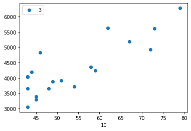
    I vs temp (only HDR 1 values)

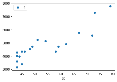
    Q vs temp( only HDR 1 values)

    I vs temp (HDR 0 values)

    I vs temp(HDR 0 values)

  • Hi Darsan,

    Can you elaborate on your first question "in OPT3101device_Functions.cpp"? I'm not sure where the question is, is it in the block of code?

    The data ready signal can be brought out through GP1 or GP2 depending on the configuration of the outputs which is shown in "Table 18. GPIO Configuration Registers" of the device datasheet.

    Have you been able to do any investigating into why the sleep time is 100 or 61440 ms? Are these long sleep times corresponding with some of the erroneous measurements for Xtalk?

  • my question is

    The data ready signal can be brought out through GP1 or GP2 depending on the configuration of the outputs which is shown in "Table 18. GPIO Configuration Registers" of the device datasheet.

    I am going through it now, as for the rest of doubts.

    as mentioned in OPT3101device_Functions.cpp

    should i use "// host.sleepDataReadyCounts(this->configurationFlags_xtalkSettlingOneTauInDataReadyCounts<<3); // This is for 8 Tau settings"

    if so while updating the code section of sleepDataReadyCounts in hostController.cpp , what interrupt we receive from opt3101.

    Have you been able to do any investigating into why the sleep time is 100 or 61440 ms? Are these long sleep times corresponding with some of the erroneous measurements for Xtalk?

    today i am working on debugging this, in lab_2 in between data readings ,where timeInMilliSeconds is set at 2048, when there is no reading taking place , timeinMilliSeconds is becoming 61440 ,maybe to bring suitable delay, earlier i as checking time take for task , now i changed function and i am seeing 2 sec (2048 millisec) for each data, and 61440 (61sec) after ever 2 data set ,maybe to bring in a delay for the cooling process. But the final data is still a mess as shown in graphs. 

    particularly value when HDR is 1 and 0 is having a very big difference of 3000 in I and 8000 in Q.

    i tried closing the photo diode and emitter separately , still we are receiving the same error, also when both are left open.

    We are wondering if there are some error while doing LAB_1 , as we believe HDR mode is the one which is messing up the graph in a major way.

    in LAB_1 we are only taking 2 reading for channel 1 , at 50cm and 55 cm ,for non HDR and HDR mod respectively.

    Could it be a factor, should the HDR mode point be placed nearly at few meters to achieve HDR .

    is there any logic for selecting these distances while calibrating?should more sets be used for calibrating channel 1.?

    will modulating frequency effect here too?-> should HDR mode be choosen according to that.

  • Hi Darsan,

    Regarding the question about HDR mode, there will be separate slope coefficients for each TX channel and HDR mode, so it won't be helpful to look at the graphs of I and Q vs temp with both HDR modes on the same figure. But looking at the graphs with each HDR mode separate, I am still seeing a lot of non-linearity and erroneous measurements, like in the I vs. Temp (HDR 0) graph.

    In regards to where the target should be placed in HDR mode, it is recommended in the How to set up and calibrate OPT3101 based systems for proximity sensing guide to choose a distance with signal amplitude between 16000 and 24000 in order to ensure that residue crosstalk is minimized. This goes for both non-HDR and HDR mode. If you are measuring at a very low signal amplitude, this will have a significant impact on your coefficients from inlab step 2.

    Thank you,

    Brent Elliott

  • Marking this thread as resolved. However if you need further help please open a new post and we can discuss further.

    Best,

    Alex

  • No our issue didn't get resolved thus i mailed Brent with all progress till now in his mail.

  • Darsan,

    I'm going to close this specific thread since we have taken the discussion offline.

    Thank you,

    Brent Elliott