This thread has been locked.

If you have a related question, please click the "Ask a related question" button in the top right corner. The newly created question will be automatically linked to this question.

IWR1642BOOST: Moving target mixed with the zero-Doppler bin (range profile) after BPM decoding

Part Number: IWR1642BOOST
Other Parts Discussed in Thread: DCA1000EVM,

Hello,

I run a BPM based raw ADC capture by using IWR1642Boost and DCA1000EVM. The scence was clear, only one person was moving away from the radar at the boresight. 

I referred this post for BPM decoding. 

My settings for BPM were

ar1.ChanNAdcConfig(1, 1, 0, 1, 1, 1, 1, 2, 1, 0)

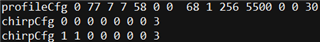
ar1.ProfileConfig(0, 77, 7, 5, 87.3, 0, 0, 0, 0, 0, 0, 42, 0, 512, 6250, 0, 0, 30)

ar1.ChirpConfig(0, 1, 0, 0, 0, 0, 0, 1, 1, 0)

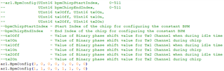
ar1.BpmConfig(0, 0, 0, 0, 0, 0, 0, 0)

ar1.BpmConfig(1, 1, 0, 0, 1, 1, 0, 0)

ar1.FrameConfig(0, 1, 300, 32, 100, 0, 0, 1)

My decoding steps are

(1)

RX1: Sa Sb Sa Sb Sa Sb Sa Sb ...

RX2: Sa Sb Sa Sb Sa Sb Sa Sb ...

RX3: Sa Sb Sa Sb Sa Sb Sa Sb ...

RX4: Sa Sb Sa Sb Sa Sb Sa Sb ...

(2) 

RX1: TX1 TX2 TX1 TX2 TX1 TX2 ...

RX2: TX1 TX2 TX1 TX2 TX1 TX2 ...

RX3: TX1 TX2 TX1 TX2 TX1 TX2 ...

RX4: TX1 TX2 TX1 TX2 TX1 TX2 ...

where TX1 = 0.5*(Sa+Sb) and TX1 = 0.5*(Sa-Sb)

(3)

RX1: TX1 TX1 TX1 TX1 ...

RX2: TX1 TX1 TX1 TX1 ...

RX3: TX1 TX1 TX1 TX1 ...

RX4: TX1 TX1 TX1 TX1 ...

RX5: TX2 TX2 TX2 TX2 ... (extract TX2 from RX1)

RX6: TX2 TX2 TX2 TX2 ... (extract TX2 from RX2)

RX7: TX2 TX2 TX2 TX2 ... (extract TX2 from RX3)

RX8: TX2 TX2 TX2 TX2 ... (extract TX2 from RX4)

It results in 300 x 32 x 8 x 512

I have two questions.

(1) After radar data processing, I found the moving target was mixed with the range profile (zero-Doppler bin). For example, the moving target is at 10m around. In the Range vs Power plot the moving target was mixed with zero-Doppler bin, which I think it is wrong (1st pic). However, with the TDM setting, moving target was not mixed with zero-Doppler bin, which is correct (2nd pic). 

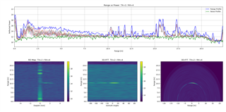
From my understanding, to get the Range vs Power plot Doppler correct is not necessarily applied.

Is there any step that I was missing for BPM decoding so that the moving target mixed with the zero-Doppler bin?

(2) From the MIMO Radar pdf (https://www.ti.com/lit/an/swra554a/swra554a.pdf?ts=1649918331937&ref_url=https%253A%252F%252Fwww.google.com%252F),

on page 7, it says BPM has a benefit of 10log10(NTX) compared with TDM configuration. 

How should interpret/understand this? In other words, which  value I should use to compare between BPM and TDM that related to 10log10(NTX)?

Thank you very much for the help!

Best,

Hang

  • It looks like you only have one chirp config set up. You will need two for the BPM to work properly. See the below example of a script setting up 2 chirps for BPM config.

    desired_interchirp_time_tr = 76
    desired_idle_time_tx2 = 7;
    ramp_end_time = 31  -- for 64 samples, will be adjusted for 48 samples
    idle_times = {desired_interchirp_time_tr-(desired_idle_time_tx2+ramp_end_time)-ramp_end_time, desired_idle_time_tx2}
    
    if(0 == ar1.ProfileConfig(0, 61.00, idle_times[1], 8, ramp_end_time, 22, 22, 22, 0, 0, 0, 99.000, 1, 64, 3000, 0, 0, 36)) then
                    WriteToLog("ProfileConfig Success\n", "green")
    else
                    WriteToLog("ProfileConfig failure\n", "red")
    end
    
    if(0 == ar1.ProfileConfig(1, 61.00, idle_times[2], 8, ramp_end_time, 22, 22, 22, 0, 180, 0, 99.000, 1, 64, 3000, 0, 0, 36)) then
                    WriteToLog("ProfileConfig Success\n", "green")
    else
                    WriteToLog("ProfileConfig failure\n", "red")
    end
    
    -- Chirp Config
    -- ChirpConfig(chirpStartIndex, chirpEndIndex, profileId, startFrequencyVariation, frequencySlopeVariation, idleTimeVariation, adcStartVariation, antennaEnableMask)
    if (0 == ar1.ChirpConfig(0, 0, 0, 0, 0, 0, 0, 1, 1, 0)) then
        WriteToLog("ChirpConfig Success\n", "green")
    else
        WriteToLog("ChirpConfig failure\n", "red")
    end
    
    if (0 == ar1.ChirpConfig(1, 1, 1, 0, 0, 0, 0, 1, 1, 0)) then
        WriteToLog("ChirpConfig Success\n", "green")
    else
        WriteToLog("ChirpConfig failure\n", "red")
    end
    

    Hopefully that helps. I am not sure about the demodulation scheme, as it is not really code, but your equation seems correct (assuming you meant Tx1 and Tx2 in the equation).

    Also, for (2), since there are 2 TX antennas being used, the BPM scheme should increase SNR by about 10*log10(2) which is about 3dB.

    Regards,

    Jackson

  • Hi Jackson, 

    Thank you very much for the help! I was referring this file (attached) for BPM raw ADC data capture. 

    C:\ti\mmwave_sdk_03_05_00_04\packages\ti\demo\xwr16xx\mmw\profiles\profile_2d_bpm.cfg

    It was using only one profile for two chirps. 

    In my configuration (I was using IWR1642Boost), I used 

    ar1.ChirpConfig(0, 1, 0, 0, 0, 0, 0, 1, 1, 0) which I thought it is equivalent to 

    ar1.ChirpConfig(0, 0, 0, 0, 0, 0, 0, 1, 1, 0) and ar1.ChirpConfig(1, 1, 0, 0, 0, 0, 0, 1, 1, 0)

    From your example, it uses two profiles for two chirps if I understand it correctly. 

    For BPM configuration, does it requires two profiles?

    Please give me 1~2 days for studying your example and testing.

    Thanks, again!

    Best,

    Hang

    5078.profile_2d_bpm.cfg

  • Hi Jackson,

    May I have a quick question on ar1.BpmConfig()?

    For my configuration for the 1st chirp both Tx1 and Tx2 has phase 0, for the 2nd chirp, Tx1 has phase 0 and Tx2 has phase 180.

    Here are my configurations.

    Does it look correct to you?

    Thanks!

    Best,

    Hang

  • Hello,

    Yes I think that looks correct. You are correct above, you do not need two chirp profiles, the example just happened to use them. But you do need two chirp configurations to switch the phase of TX2 in the second config. The BPMconfg will only control the demodulation, not the TX output, so you need these to match.

    Regards,

    Jackson