This thread has been locked.

If you have a related question, please click the "Ask a related question" button in the top right corner. The newly created question will be automatically linked to this question.

AFE3010: AFE3010

Part Number: AFE3010

AFE3010: Several questions

(+) AFE3010: Several questions - Sensors forum - Sensors - TI E2E support forums

Hi team,

As per mention above thread how would you find out value of RFB = 36kOhm, give detail description on that.

And can you please give all the formula guide to related this application note?

Thanks 

Parth Bhavsar

  • Hey Parth,

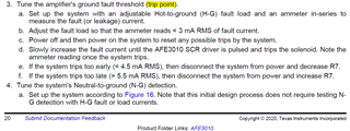
    In the datasheet, there is a simple trial and error method that does not require measuring the impedance of the 1000:1 coil. The procedure basically is adjusting RFB until the device first trips at a 5mArms typical threshold set by the 5mArms comparators at 2.75V and 2.25V. This equates to a 500mV peak-peak signal at Vout pin of device set with a 2.5V bias voltage. Vout >2.75V triggers the -5mA*SQRT(2) peak comparator and Vout < 2.25V triggers the +5mA*SQRT(2) (Vout is 180 degrees out of phase with LINE).

    Once the threshold is set, all other greater threshold current will scale accordingly. The symmetrical comparator levels for ~10mArms, ~30mArms, and ~50mArms are 2.95V&2.05V, 3.85V &1.1V, and 4.8V & 0.2V respectively. The higher the comparator tripped, the faster the response time for tripping SCR and solenoid.

    Hope this makes sense.

    Sincerely,

    Peter

  • As per our requirement we want to trip system if fault current is above +/-20mA. Can you suggest Feedback resistor &  Input resistor value for the same?

    Regards,

    Parth Bhavsar

  • Hey Parth,

    Gain is heavily proportional to RFB (only when Rin is constant), thus consider reducing RFB =36kOhm by 4x yielding 9kOhm as a starting point. Although it very possible that reducing RFB this low could cause circuity instability. One way to stabilize the resonance is to increase the differential coil capacitor which has dominating affect on keeping the internal amplifier network stable. Or another way is to increase Rin. If you need to increase Rin, make sure to re-check the trip level as changing Rin can have non-linear affect on overall gain.

    You could simply increase Rin to decrease gain, but doing this can reduce performance of the neutral-to-ground fault detection from 5-Ohms to something lower. Adjust Rin in small increments.

    The amplifier is a current-feedback amplifier and is directly measuring coil current with a gain proportional to RFB/Zin where Zin includes impedance of transformer. Thus I cannot give an exact value for all transformers. However, as long as Zin is kept the same you can think a change in gain as the proportional change in RFB at least as a starting point. You can think of gain as Vpp/Arms where Arms is the actual fault current on line. So a change of the trip point from 5mA to 20mA means you'll need to decrease overall gain. 

    Sorry I cannot give you an exact answer here.

    Sincerely,

    Peter