This thread has been locked.

If you have a related question, please click the "Ask a related question" button in the top right corner. The newly created question will be automatically linked to this question.

AWR6843ISK: XDS110 Com ports not loading properly

Part Number: AWR6843ISK
Other Parts Discussed in Thread: MMWAVEICBOOST

I am trying to connect and communicate with my AWR6843ISK EVM or run the MMWAVE demo visualizer. 

My setup is as follows - AWR6843ISK board by itself(not plugged into a carrier board), USB cable plugged into J5 and connected to PC with the MMWAVESDK installed. 

When I plug in the board the following happens:

1) 4 LED's light up on the EVM - power(orange), 5V(green), reset (green) and USB enumerating (green). I also hear the sound indicating a USB device was attached

2) After a few seconds the USB enumerating LED turns off

3) In device manager, I see two new ports but they both show the warning triangle. Instead of showing as XDS110 Class ports, they just appear as "Enhanced Com Port" and "Standard Com Port" with no COM numbers assigned. Device status for these ports says "the drivers for this device are not installed (Code 28)".

This is preventing me from communicating with the EVM. 

I have tried the following:

Downloading and installing the both the XDS Emulation Software (32 and 64 bit versions) and the XDS110 Support Utilities from the link below.

https://software-dl.ti.com/ccs/esd/documents/xdsdebugprobes/emu_xds_software_package_download.html

Also have tried to manually update the driver and point it directly to the XDS110 driver at C:\ti\ccs_base\emulation\windows\xds110_drivers

Also tried rebooting the PC, and tried providing external power via TP12 and TP13 - cannot get these ports to be recognized properly. 

Do I need an actual version of CCS installed for this to work? The documentation seems to suggest this is not necessary but that seems like the only thing else I know to try.

  • Small update - I unstalled CCS and tried again. This did not help...

  • Hi Chris,

    The AWR6843ISK does not have an XDS110 onboard. If you want to debug using the XDS110, you will need to attach the board to the MMWAVEICBOOST. If you are just trying to flash and run the board without debugging, you will be utilizing the Silicon Labs UART-USB bridge which IS onboard the AWR6843ISK. This is the "standard" and "enhanced" ports that you are seeing. Let me know if you have any further questions.

    Best Regards,
    Alec

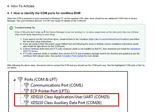
  • When I try to use the DemoVisualizer as suggested in the mmwave_sdk_user guide, the serial ports do not show up in that tool. The user guide makes it clear that they are looking for XDS110 ports (see the image below). Even if the ports dont have to be XDS110, I would assume they need to be assigned a COM port number with a valid driver. This is not happening now, as I get the yellow warning triangle in Device Manager and the status says there was no driver installed. 

    The visualizer is at this link :  https://dev.ti.com/gallery/view/mmwave/mmWave_Demo_Visualizer/ver/3.5.0/

    Do I need to also have a carrier board to use the visualizer? The documentation says I need a "mmWave TI EVM". It seems like the AWR6843ISK fits that description. 

    If not, and I would need another board to use the visualizer - what can I do with just the AWR6843ISK board? 

    I do not specifically want to debug with an XDS110, I was just trying to use the visualizer as that is what is shown as the first step in the mmwave SDK user guide. 

    I really just need to load firmware to the device and communicate with it to verify proper operation - I dont need to visualize RF images, etc

    If I can get to where I can flash LED's, toggle port pins, etc. that will be adequate for now. 

    Thanks - Chris

  • Ok -on further attempts, I was able to get the ports to show up by manually installing the Silicon Labs drivers from here:

    www.silabs.com/.../device.cp2105

    They do not show up as XDS110 ports, so I cannot use the visualizer or flash firmware as described in the mmwavesdk user guide. However they do have drivers and COM numbers now so I can try to talk over them - but I don't have any info about the command set or protocols.

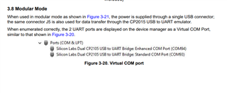
    It is setup in "Modular Mode" as described in the mmwave sensor EVM's documentation shown below:

    I am not sure what I can actually accomplish in this mode, and can't find any further discussion of how to work with the tool in this mode. Has anyone worked with the AWR6843ISK by itself using this modular mode, or do you know of any reference materials to help with this? 

    If not it looks like I will need to find a way to buy a MMWAVEICBOOST board... the documentation does not make it clear at all that this is also required. 

    -Chris

  • Hi Chris,

    I would recommend you take a look at the out of box demo users guide which is part of the mmWave Industrial toolbox which can be found here under "mmWave Sensors" : https://dev.ti.com/tirex/explore

    It contains a full step by step guide with additional details. 

    Without the MMWAVEICBOOST, you are still fully able to flash the device and run the code with our visualizers. The only limitation would be if you wanted specific additional IO that may not be exposed on the board, or if you want to debug your code step-by-step (which requires the XDS110). Let me know if you face further issues.

    Best Regards,
    Alec 

  • Alec,

    Thanks for the additional information. I finally found the Out of Box users guide which has a lot of information. I will dig through that to see if I can figure it out, but it looks likely. Once I have loaded the project into CCS and re-flashed with a custom image I should be mostly where I need to be. 

    I also tried the demo Visualizer tool again after installing the Silicon Labs ports and was able to get it to talk to the board and show plots even without the COM ports showing as XDS110 ports. So the basic demo is working now as well. 

    I would say the COM port issue is resolved now - I could still benefit from a lot more info related to the code image format stored on the QSPI flash and the serial command structure, but I will try to figure those out on my own. 

    -Chris