Hi,
We are facing some issues with our latest product. It seems that the decay time is not consistent between different pcbs and it is not very similar to the one we see on the PGA460 evaluation board BOOSTXL.
We have done hundred of tests. I will try to summarize in a few lines the issue we have so maybe you can shed some light here.
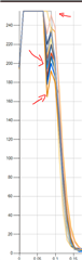
Until now we have produced around 30K pcbs and all of them behave similar. but now we created a new product (Alll schematics related to PGA460 are the same as the previous one, no changes here) And some of the pcbs (mounted by our electronical engineer not a mounting factory) show the following pattern on the decay time:

If the pcb is good, the decay time starts from the top of the chart as shown in a very few of the curves.
After replacing the transformer, some of the pcbs showed a better behavior but other did not.
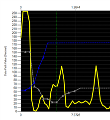
Then, we tried comparing the signal from the TEST pin of the PGA460 (TEST_MUX register set to 0x20) and the signal of the transduder and we see this on our pcbs (an almost good pcb as the issue is very small):

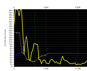
But, repeating this test on the PGA460 evaluation board BOOSTXL, shows the following:

Whis is a bit longer than expected.
If we compare 2 curves from the pga from our pcb and the PGA460 eval board (Focused only on the decay time, not the echo response):

The evaluation board decay time is a bit longer and we do not see any issue on the top of it.
We have not seen any wrong behavior on the sensor response. Echo seems to be ok, peak and wide too and thermal chamber showed the same. But we are not fully satisfied as we do not know the root cause for this issue.
Schematics are the same as shown on the reference manual. 1 transducer (Murata MA58MF14-7N).
I do not know if we could improve this behavior by configuration. Is it possible that some of the registers could modify it? I do not know, for example DEADTIME (We do not know what this register does).
If you need more information, we can provide it.