This thread has been locked.

If you have a related question, please click the "Ask a related question" button in the top right corner. The newly created question will be automatically linked to this question.

AWR1843AOP: Data getting placed in big endian if we use RAM_model

Part Number: AWR1843AOP

Hello,

We have created 10 sections in TCMB RAM 4bytes each .

Section Start address Length in bytes Model for compilation
1 0x8002A00 4 ROM_MODEL
2 0x8002A04 4 ROM_MODEL
3 0x8002A08 4 ROM_MODEL
4 0x8002A0C 4 ROM_MODEL
5 0x8002A10 4 ROM_MODEL
6

0x8002A14

4 RAM_MODEL
7 0x8002A18 4 RAM_MODEL
8 0x800 2A1C 4 RAM_MODEL
9 0x800 2A20 4 RAM_MODEL
10 0x800 2A24 4 RAM_MODEL

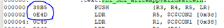
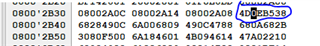
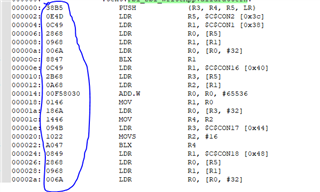
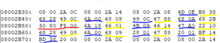
 We generate 2 hex files , Hex file one has   sections 1 to 5 and Hex file two has section 6 to 10 .when we place them on ram ,Section 1 to 5 are    placed in little endian and section 6 to 10 are placed in big endian .

(We use ROM model for compiling Hex file one and RAM model for compiling Hex file two , please refer attached image for reference how they placed in ram memory , this image is captured during debugging .

Compiler used : T_ti  arm V18.12.2  )  

WE EXPECT SECTION 6 TO 10 SHOULD ALSO BE PLACED IN LITTLE ENDIAN . Could you please provide us a solution or comment on what we are doing wrong.

  • Hi,

    Can you please let me know how I can reproduce this issue?

    Thank you

    Cesar

  • Hello cesar 

    Please refer attached file .

    Please Follow below steps 
    
    *******************************************BACKGROUND***************************************************
    
    we have 2 C files, File_1 and File_2 . We have seperate linker file for them LINKER_1 and  LINKER_2 and compile them independently to generate two hex files .
    Hex File_1 is loaded in controller and runs as a normal embedded code , now we write hex File_2 to ram area of controller by a external tool .
    
    
    ************************************File_1 setup steps start **************************************************
    
    Compiler : T_ti arm V18.12.2
    Model	 : ROM model
    
    LINKER_1 discribtion :
    (Please create required section for your code eg: .text , .cinit , .bss etc according to your requirnment in the below example we have just explained you what we are trying to do)
    
    ***************************************************************************************************************************
    							MEMORY{
    											FUNCTION_POINTER_AREA(RW)     : origin=0X08002A00    length = 0x28
    								  }
    								  
    							SECTION{
    									 GROUP : > FUNCTION_POINTER_AREA   ALIGN(4)
    										{
    											Function_1_SECTN		
    											Function_2_SECTN
    											Function_3_SECTN
    											Function_4_SECTN		
    											Function_5_SECTN
    											
    											Function_6_SECTN			type = NOINIT
    											Function_7_SECTN   			type = NOINIT
    											Function_8_SECTN   			type = NOINIT
    											Function_9_SECTN            type = NOINIT
    											Function_10_SECTN           type = NOINIT
    										}
    									}
    
    
    ********************************************************************************************************************************
    
    File_1 discribtion :
    
    File_1 has 6 functions  as follows void Function_1(void), void Function_2(void), void Function_3(void), void Function_4(void), void Function_5(void) and void Function_11(void) ;


    		#pragma DATA_SECTION(Function_6_PTR, "Function_6_SECTN")				  
    		void (*Function_6_PTR)();
    		
    		#pragma DATA_SECTION(Function_7_PTR, "Function_7_SECTN")				  
    		void (*Function_7_PTR)();
    		
    		#pragma DATA_SECTION(Function_8_PTR, "Function_8_SECTN")				  
    		void (*Function_8_PTR)();
    		
    		#pragma DATA_SECTION(Function_9_PTR, "Function_9_SECTN")				  
    		void (*Function_9_PTR)();
    		
    		#pragma DATA_SECTION(Function_10_PTR, "Function_10_SECTN")				  
    		void (*Function_10_PTR)();


    		  void main()
    		  {
    			Function_11();
    		  }
    		  
    		  void Function_11(void)
    		  {
    			Function_6_PTR();
    			Function_7_PTR();
    			Function_8_PTR();
    			Function_9_PTR();
    			Function_10_PTR();
    		  }
    		  
    		  void Function_1(void)
    		  {
    			/*user code*/
    		  }
    		  void Function_2(void)
    		  {
    			/*user code*/
    		  }
    		  void Function_3(void)
    		  {
    			/*user code*/
    		  }	  
    		  void Function_4(void)
    		  {
    			/*user code*/
    		  }	  
    		  void Function_5(void) 
    		  {
    			/*user code*/
    		  }	  
    						  
    		#pragma RETAIN(Function_1_PTR)
    		#pragma DATA_SECTION(Function_1_PTR, "Function_1_SECTN")				  
    		void (*Function_1_PTR)() = void Function_1;
    		
    		#pragma RETAIN(Function_2_PTR)
    		#pragma DATA_SECTION(Function_2_PTR, "Function_2_SECTN")				  
    		void (*Function_2_PTR)() = void Function_2;
    		
    		#pragma RETAIN(Function_3_PTR)
    		#pragma DATA_SECTION(Function_3_PTR, "Function_3_SECTN")				  
    		void (*Function_3_PTR)() = void Function_3;
    		
    		#pragma RETAIN(Function_4_PTR)
    		#pragma DATA_SECTION(Function_4_PTR, "Function_4_SECTN")				  
    		void (*Function_4_PTR)() = void Function_4;
    		
    		#pragma RETAIN(Function_5_PTR)
    		#pragma DATA_SECTION(Function_5_PTR, "Function_5_SECTN")				  
    		void (*Function_5_PTR)() = void Function_5;
    
    
    ************************************File_1 setup steps END **************************************************
    
    
    ************************************File_2 setup steps start **************************************************
    
    Compiler : T_ti arm V18.12.2
    Model	 : RAM model
    
    LINKER_2 discribtion :
    (Please create required section for your code eg: .text , .cinit , .bss etc according to your requirnment in the below example we have just explained you what we are trying to do)
    ***************************************************************************************************************************
    							MEMORY{
    											FUNCTION_POINTER_AREA(RW)     : origin=0X08002A00    length = 0x28
    								  }
    								  
    							SECTION{
    									 GROUP : > FUNCTION_POINTER_AREA   ALIGN(4)
    										{
    											Function_1_SECTN   			type = NOINIT		
    											Function_2_SECTN   			type = NOINIT
    											Function_3_SECTN   			type = NOINIT
    											Function_4_SECTN   			type = NOINIT		
    											Function_5_SECTN   			type = NOINIT
    											
    											Function_6_SECTN			
    											Function_7_SECTN   			
    											Function_8_SECTN   			
    											Function_9_SECTN            
    											Function_10_SECTN           
    										}
    									}
    
    
    ********************************************************************************************************************************
    
    File_2 discribtion :
    
    File_2 has 5 functions  as follows void Function_6(void), void Function_7(void), void Function_8(void), void Function_9(void), void Function_10(void).


    		#pragma DATA_SECTION(Function_1_PTR, "Function_1_SECTN")				  
    		void (*Function_1_PTR)();
    		
    		#pragma DATA_SECTION(Function_2_PTR, "Function_2_SECTN")				  
    		void (*Function_2_PTR)();
    		
    		#pragma DATA_SECTION(Function_3_PTR, "Function_3_SECTN")				  
    		void (*Function_3_PTR)();
    		
    		#pragma DATA_SECTION(Function_4_PTR, "Function_4_SECTN")				  
    		void (*Function_4_PTR)();
    		
    		#pragma DATA_SECTION(Function_5_PTR, "Function_5_SECTN")				  
    		void (*Function_5_PTR)();


    		  void Function_6(void)
    		  {
    			Function_1_PTR();
    		  }
    		  void Function_7(void)
    		  {
    			Function_2_PTR();
    		  }
    		  void Function_8
    			Function_3_PTR();
    		  }	  
    		  void Function_9(void)
    		  {
    			Function_4_PTR();
    		  }	  
    		  void Function_10(void) 
    		  {
    			Function_5_PTR();
    		  }	  
    						  
    		#pragma RETAIN(Function_6_PTR)
    		#pragma DATA_SECTION(Function_6_PTR, "Function_6_SECTN")				  
    		void (*Function_6_PTR)() = void Function_6;
    		
    		#pragma RETAIN(Function_7_PTR)
    		#pragma DATA_SECTION(Function_7_PTR, "Function_7_SECTN")				  
    		void (*Function_7_PTR)() = void Function_7;
    		
    		#pragma RETAIN(Function_8_PTR)
    		#pragma DATA_SECTION(Function_8_PTR, "Function_8_SECTN")				  
    		void (*Function_8_PTR)() = void Function_7;
    		
    		#pragma RETAIN(Function_9_PTR)
    		#pragma DATA_SECTION(Function_9_PTR, "Function_9_SECTN")				  
    		void (*Function_9_PTR)() = void Function_9;
    		
    		#pragma RETAIN(Function_10_PTR)
    		#pragma DATA_SECTION(Function_10_PTR, "Function_10_SECTN")				  
    		void (*Function_10_PTR)() = void Function_10;
    		
    		
    ************************************File_2 setup steps END **************************************************
    
    Now compile the File_1 and observe its map file and hex file , it is observed that in __TI_cinit_table you can see their load and run address , and when you run the code  it is placed in little endian on ram ,
    and if you dump the File_2 hex file the   section  Function_6_SECTN , Function_7_SECTN ,Function_8_SECTN ,Function_9_SECTN ,Function_10_SECTN  are placed in big endian on ram.
    

  • Hello any update on this ? , do you need any more information ?

  • Based on my experience with similar situations, every little detail matters.  I appreciate all the work that went into the text file description of how to reproduce the problem.  Unfortunately, lots of detail is lacking.  I'll give you some ideas on what to look at that may narrow the scope of the problem, and that may make it easier to submit a test case which allows us to reproduce the problem.

    The general idea is to find the first moment the endianness is wrong.  

    For each build, compare the final executable files generated by the linker.  These files usually have the file extension .out.  In the same \bin directory as the compiler armcl, there is a standalone disassembler named armdis.  From a command line prompt, issue a command similar to ...

    armdis --all final_executable.out > final_executable_dis.txt

    Do that for each build.  Compare the endianness you see in each file.  Is it what you expect?

    Next, look at the hex files created for each build.  To understand those files, you need to know the details of the hex format.  For that, please search the TI ARM assembly tools manual for the sub-chapter titled Description of the Object Formats.  Compare the endianness you see in each file.  Is it what you expect?

    It might be the case that the endianness is correct in both the final executable files and the hex files.  If so, it becomes a question of how the hex files are loaded (or flashed or whatever) into system memory.

    Thanks and regards,

    -George

  • hello 

    Thankyou for your valuable feed back, as u mention lots of detail is lacking , If you list them i can provide you the details , so that you can reproduce the problem.

  • Please perform the first experiment I describe, where you use armdis to look at the disassembly of the final executable file.  Is the endianness in each file correct?

    Thanks and regards,

    -George

  • Hello 

    I did the experiment following is the out come .

    As requested we used armdis --all command and generated the text file below you can see a screen shot from it .  

    Image taken from object > text file

    In the 2nd image you can see how data is placed on ram in controller

    so yes there is difference between them , please let me know if you want some more information  .

  • conclusion 

    For file_1 which i am compiling with ROM model, the data on ram matches with the generated text file(CHANGE IN ENDIAN)

    But for file_2 which i am compiling with RAM model the data on ram is not matching with generated text file (NO CHANGE IN ENDIAN)  

  • Please compare the two builds against each other at the same stage.  Compare the two .out files, the standalone disassembly of those two files, the two hex files, the disassembly view in the debugger for those two files, etc.  At what point in that progression does the mismatch of endianness first appear?  So far, you have not done this analysis.

    I suspect this might be problem of misunderstanding the display.  To show what I mean by that, I’ll give an example.  The only ARM hardware I have on hand has a Cortex-M4F CPU in it.  Your system has a Cortex-R4F CPU in it.  But it appears you build for the Thumb2 code state, which is the only code state supported by Cortex-M4F.  So, as used here in this post, those two CPU's are similar enough.

    Your screen shot shows the beginning of a function.  It starts with two 16-bit instructions.  It is located at an address that is 8-byte aligned.  For a program I am running, I found a function with those same conditions.

    Here is the standalone disassembly view …

    0006cc:              _getarg_diouxp___TI_printfi_nofloat:
    0006cc: 027B             LDRB            R2, [R0, #12]
    0006ce: 702A             CMP             R2, #112

    What order are those 4 bytes as laid out in the .out file?  By methods I don’t show here, I determined that the file offset for the section which contains this code is 0x34 bytes.  So, to see these bytes in the file, start looking at byte offset 0x34 + 0x6cc = 0x700.

    Here is one command to do that …

    % od -Ax -t x1 -w4 -j 0x700 file.out
    000700 02 7b 70 2a

    I load file.out into CCS with the usual load command.  Here is the disassembly view …

    Here is how it looks in a memory browser that is configured to look at 32-bits at once …

    In that same memory browser, change the configuration to look at 8-bits at a time …

    Notice how the order of the bytes does not match.  This code executes correctly, so everything must be correct.  The difference must lie in how these displays are implemented.  I cannot explain how and why these different displays handle endianness differently.  I only know, by direct experimentation, that it works.

    Perhaps your situation can be explained in a similar way.

    Thanks and regards,

    -George

  • Hello

    Thankyou for your reply  It is not problem with display , i checked the hex file, it has changed   endian compered to the generated text file . i am attaching hex file screenshot and generated text file screenshot for your reference. 

    fig 1 :- Generated txt file screenshot.

    fig 2 :- HEX file screenshot.

  • I suggest we back up a bit.  In your first post, you say ...

    We use ROM model for compiling Hex file one and RAM model for compiling Hex file two

    Based on that, I presume you have two different .out files that are created by the linker.  If this presumption is wrong, then everything else I have said is wrong.

    For those two .out files, disassemble them with the standalone disassembler armdis.  Compare the output.  Is the endianness in each file as expected?

    Thanks and regards,

    -George

  • hello george 

    Yes we use ROM model for file one and RAM model for file two . File one is ok , but file two has changes endian.

  • we use ROM model for file one and RAM model for file two

    For each file, please show a bit of the output of armdis which demonstrates the endianness problem.

    Thanks and regards,

    -George