This thread has been locked.

If you have a related question, please click the "Ask a related question" button in the top right corner. The newly created question will be automatically linked to this question.

IWR1443BOOST: The internal workflow of the radar when capturing ADC data

Part Number: IWR1443BOOST
Other Parts Discussed in Thread: DCA1000EVM

Dear Engineer,

I am using IWR1443BOOST+DCA1000EVM+ MMWave Studio to capture raw ADC data.

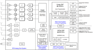
I would like to know what procedures or steps the radar equipment or its sub-modules have gone through in the process of generating oscillation signal, transmitting signal from antenna, receiving echo signal and output complex adc_data.bin, etc.

Can you just tell me or provide me with a resource book or something? Let me have a clearer understanding of the equipment.

Thank you very much!

  • In particular, what happened in the process of receiving antenna to get ADC_data.bin after receiving the echo signal, and what processing was carried out on the echo signal.

  • HI, Kelong:

    You can find a block diagram in the device datasheet.  Please check on the device datasheet document.   An example is given: 

    You can see that at the receive side, the received signal is going through LNA, and mixed with transmit signal, then go through IF band filtering and amplifier before going to the ADC. 

    Best,

    Zigang

  • HI, Zigang:

    Is this "IF Band Filtering" the same thing that I've circled?

    If it is, then it means that the output of the mixing signal has gone through a high-pass filtering.

    So when I use radar to measure low frequency moving targets, which is lower than the cutoff frequency, does it cause signal distortion? How can I avoid it or fix it?

    Best,

    Kelong

  • HI, Kelong:

    The ADC is sigma-delta ADC.  It sampled at very high rate and followed with several stages of digital down-sampler before gets to the ADC sampling rate that customer configure.   All the digital down-sample stages has very sharp low pass filter.  So, users will not have aliasing problem.  But the highest IF bandwidth is about 90% of ADC sampling rate due to the low pass filter.  For example, if we program the ADC rate to be 5MHz, then the highest IF frequency supported in this configuration is about 5*90% = 4.5MHz. 

    Best,

    Zigang

  • HI, Zigang:

    Is the output of mixer I signal and Q signal? If so, how do I signals and Q signals come from, respectively? What is the relationship with the complex numbers in the final adc_data.bin?

    Best,

    Kelong

  • Hi, Kelong:

    The TX signal and its 90 degree phase shifted version are sent over to mixer to create I and Q signals.  You can google complex RF mixer for general idea. 

    Best,

    Zigang