Hi All
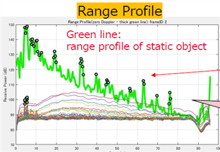
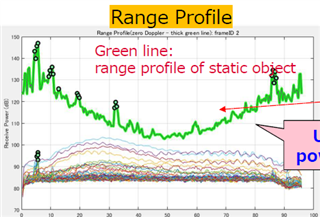
In AWR2243 cascade radar, we have dumped ADC data using TI's default object detection use case radar configuration (35m config). While analyzing the range profile plot, we are observing a U-shaped curve, if plotted in dB. We had collected the data in the general working area facing the room and hence there will be no objects to be detected beyond 15-20m. Please note that this U shape profile is not seen in the Range profile if the amplitude is plotted. It is seen only when the power (10 log) is plotted in dB.
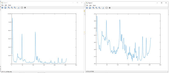
Both plots are shown below for reference:
Fig1 > Range profile with amplitude
Fig2> Same Range profile with power value in dB (10log)
Please let us know if this is an expected profile for long-range or if there is any reasoning behind this.
Thanks & Regards
Vishnu