


Hello,
We have a PGA460 included in the PCB of one of our devices. In particular, it's a transformer driven system. We've been recently observing some irregularities on the emision section, so we looked closer our design to try to find if it might be related to the pasive components.
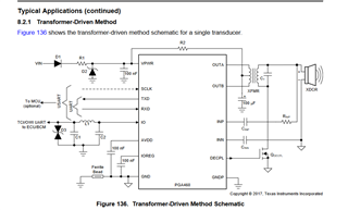
After some testing, we've observed they are directly related to the values of resistors RINP and capacitors CINP and CINN.
We initially gave them the values suggested at your datasheet, detailed in the table 101 of that document.
Nevertheless, as changing them for tests caused effects not expected, we were wondering:
- Could you tell us which is the function of those three elements? We've been searching for them in the datasheet, but couldn't find enough information.
- We've observed that the values suggested are not the same ones as those you implement on the BOOSTXL-PGA460 evaluation board. (Suggestion is 3 KOhm, but in your device its value is 100 Ohm) Is there any reason for that? We're asking just in case it could help us with our application.
Thanks in advance for the help.
