Other Parts Discussed in Thread: MMWAVEICBOOST
Hi Everybody,
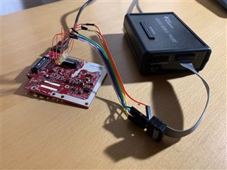
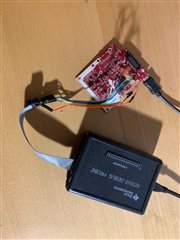
I bought an XDS110 Debug Probe (Datasheet here https://www.ti.com/lit/ug/sprui94/sprui94.pdf?ts=1651406157309&ref_url=https%253A%252F%252Fwww.ti.com%252Ftool%252FTMDSEMU110-U) and I am trying to connect it to my AWR6843ISK.
My connections are as follows.
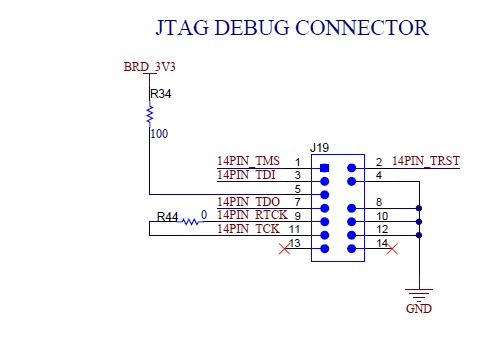
| AWR6843ISK J1 60 Pin HD Connector | XDS110 Debug Probe Debug |
| Pin13 TADAR_TMS | Pin1 SWDIO/TMS |
| Pin12 RADAR_NRST_1 | Pin2 NTRST |
| Pin11 RADAR_TDI | Pin3 TDI |
| Pin4 VCC_3V3 | Pin5 VTREF |
| Pin17 RADAR_TDO_SOP0 | Pin7 SWO/TDO |
| Pin20 GND | Pin8 GND |
| Pin15 RADAR_TCK | Pin11 TCK |
I loaded the Debug Software onto the Radar Module. I power the Debug Probe with its USB and the Radar as well over the Micro USB. When I am testing my target configuration in Code Composer I get the following output
[Start: Texas Instruments XDS110 USB Debug Probe_0]

Execute the command:

%ccs_base%/common/uscif/dbgjtag -f %boarddatafile% -rv -o -S integrity

[Result]


-----[Print the board config pathname(s)]------------------------------------

/home/christoph/.ti/ccs1110/0/0/BrdDat/testBoard.dat

-----[Print the reset-command software log-file]-----------------------------

This utility has selected a 100- or 510-class product.
This utility will load the adapter 'libjioxds110.so'.
The library build date was 'Dec  8 2021'.
The library build time was '11:12:50'.
The library package version is '9.6.0.00172'.
The library component version is '35.35.0.0'.
The controller does not use a programmable FPGA.
The controller has a version number of '5' (0x00000005).
The controller has an insertion length of '0' (0x00000000).
This utility will attempt to reset the controller.
This utility has successfully reset the controller.

-----[Print the reset-command hardware log-file]-----------------------------

The scan-path will be reset by toggling the JTAG TRST signal.
The controller is the XDS110 with USB interface.
The link from controller to target is direct (without cable).
The software is configured for XDS110 features.
The controller cannot monitor the value on the EMU[0] pin.
The controller cannot monitor the value on the EMU[1] pin.
The controller cannot control the timing on output pins.
The controller cannot control the timing on input pins.
The scan-path link-delay has been set to exactly '0' (0x0000).

-----[An error has occurred and this utility has aborted]--------------------

This error is generated by TI's USCIF driver or utilities.

The value is '-233' (0xffffff17).
The title is 'SC_ERR_PATH_BROKEN'.

The explanation is:
The JTAG IR and DR scan-paths cannot circulate bits, they may be broken.
An attempt to scan the JTAG scan-path has failed.
The target's JTAG scan-path appears to be broken
with a stuck-at-ones or stuck-at-zero fault.

[End: Texas Instruments XDS110 USB Debug Probe_0]
Is there anybody that could help with the issue. Am I missing some connection or something?
Best,
Christoph