This thread has been locked.

If you have a related question, please click the "Ask a related question" button in the top right corner. The newly created question will be automatically linked to this question.

OPT3101: SDK Calibration Problems

Part Number: OPT3101

Hello,

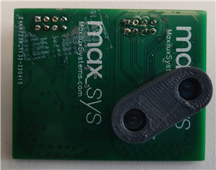
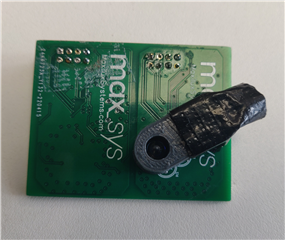
I have designed a custom board and used ESP32 as host.

I am using SDK to configure and calibrate the OPT3101. I have few queries.

1. I am using only one emitter channel , i.e., TX0. 

I wanted to ask if I am required to make any changes on OPT3101_configuration.cpp file to let OPT3101 know the I am only using one emitter channel? Also, I am interested in using HDR mode High. But i noticed that as soon as I change reg.en_adaptive_hdr from 1 to 0. I start getting 0 as a result.

2. I followed SDK manual to calibrate the design. The procedure i am following is as follows:

      STEP 0: IN_LAB_STEP 0: dev.resetInitAndViewData(3000, false);

                     Here, I masked the photodiode using electric tape and to ensure that there is no light leaking, I did the same with LED and viewed using IF camera and found that no light was leaking through the masking tape.

                     Result:  I, Q,S, ScaledI, ScaledQ,tMain,tIlum,tMain(C), tIlum(C),Magnitude
                                 -025936,+003728,0,-0025936,+0003728, 0000, 0000, +00, -128.0000, 84.7

Attached image for the output of STEP 0:

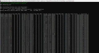
The magnitude I get is 84.7. Is this magnitude is the representation of raw crosstalk? 

I am getting high amplitude on TX0 = around 18500. Is this something I should not be worried about in STEP 0?

                   STEP 1: IN_LAB_STEP 1: dev.calibrationSession_firstTimeBringUp();

                                                              dev.resetInitAndViewData(3000, true);

Attached image for the output of STEP 1:

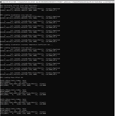
I am not sure if this setup is correct. Can you please guide me through it?

I have not done system calibration yet.

Regards

Heena

  • Hi,

    1. Use the configurator tool online to generate the config.cpp file. 

    2. Is this magnitude is the representation of raw crosstalk? yes

    I am getting high amplitude on TX0 = around 18500. Is this something I should not be worried about in STEP 0? yes - if photodiode is masked correctly you should not be getting this high unless you are using a custom board with incorrect design. EVM has around 200 codes max. You may want to test with EVM to see if you have board issues.

    Have you seen this? https://e2e.ti.com/support/sensors-group/sensors/f/sensors-forum/815766/faq-opt3101-what-are-the-resources-ti-provides-for-developing-with-opt3101 

    We have lots of documentation and resources - these are all linked there.

    Best,

    Alex

  • Hi Alex,

    Thank you for your reply.

    I have used the configurator tool to generate .cpp file. And i am currently using TX0 with non-HDR mode. HDR_mode set to 1.

    when I run step_0, I am getting internal crosstalk magnitude =82.8 and amplitude is 635.

    INFO::Performing Internal Cross talk Measurement...
    INFO::Internal Cross talk Measurement Completed
    I, Q,S, ScaledI, ScaledQ,tMain,tIlum,tMain(C), tIlum(C),Magnitd
    -024109,+008053,0,-0024109,+0008053, 0000, 0000, +00, -128.0000, 82.8


    |Distmm, Phase,Amplud,SigS,AmbS,HDR|--|Distmm, Phase,Amplud,SigS,AmbS,HDR|--|Distmm, Phase,Amplud,SigS,AmbS,HDR|--|Amb,Cntr,Tmain,Tillum | Count/Total |
    |000000,000000,000635, 0, 0, 1|--|000000,000000,000000, 0, 0, 0|--|000346,001517,000615, 0, 0, 1|--|066,0x13, +31,-128.0000|0000299/0000300|

    After this, I run step_1. This results in internal crosstalk magnitude = 76.5 and illumination crosstalk magnitude = 528.5.

    I have done 

    dev.calibrationSession_perDesignCalibrationCrosstalkTemp();   //Step_2

      dev.calibrationSession_perDesignCalibrationPhaseTemp();    //step_3
     
    I am following OPT3101-SDK and how to setup and calibrate OPT3101 files for calibration.
    I have followed EVM and other documentation while designing the board.
    But i am not sure if the results I am getting is right or not. Can I get some help with the design of the board to know if the PCB layout is the problem?
    Regards
    Heena 
  • Ok - 528 is not horrible but also not ideal. You should be able to at least calibrate out that level and test performance. Please refer to the intro to system design doc in the linked e2e. It is a long doc but gives many useful details. It has sections on PCB design you can review and cross check with your design.

    Best,

    Alex

  • Hi Alex,

    Thank you for your help.

    Can you please tell me the ways i can troubleshoot this?

    Thank you

    Heena

  • Hi Heena,

    You should be able to calibrate with your measured crosstalk amplitude and the system design doc will provide the necessary details for reviewing your design. If you need more help let me know.

    Thank you,

    Brent Elliott

  • Hi Brent,

    Thank you for the reply.

    Can I share my OPT design and get some insight on that?

    Thank you

    Regards

    Heena

  • Hi Heena,

    My apologies, but we will not be able to review the design. However, as mentioned we have created the system design doc and put all needed details in the doc so these should be able to help you understand if there is any issue in the design. If there is something missing from the doc you can let us know and we can check for the missing info.

    Best,

    Alex

  • Hi,

    Thanks for your help.

    Can you please tell me that once each calibration is done, how to verify if the calibration coefficients are right?

    Regards

    Heena

  • Hi I have managed to bring the raw crosstalk considerably low.

    INFO::Performing Internal Cross talk Measurement...
    INFO::Internal Cross talk Measurement Completed
    I, Q,S, ScaledI, ScaledQ,tMain,tIlum,tMain(C), tIlum(C),Magnitd
    -001243,+001300,0,-0001243,+0001300, 0000, 0000, +00, -128.0000, 5.9


    |Distmm, Phase,Amplud,SigS,AmbS,HDR|--|Amb,Cntr,Tmain,Tillum | Count/Total |
    |009800,042851,000036, 0, 0, 1|--|066,0x00, +31,-128.0000|0000299/0000300|

    I have done all the calibrations as well. but I want o make sure that after very calibration, I am getting closer to precise values.

    So, can you please tell me how can I verify the changes after each calibration?

    Regards

    Heena

  • Hi Heena,

    Calibration values should be consistent if you recalibrate multiple times.

    Also make sure you are masking the photodiode correctly for the illumination crosstalk calibration process.

    Can you confirm magnitude value for both internal and illumination xtalk and I can check it

    Best,

    Alex

  • Also share a picture of the board with and without photodiode masked

    Best,

    Alex

  • Hi Alex,

    The magnitude value with photodiode covered for internal crosstalk is 13.3 and illumination crosstalk is 0.

    One thing i am noticing is that while my photodiode is masked, the amplitude varies from very low to very high values through the frame count. I don't understand the exact reason for that. Can you help me understand that.

    Images are attached below:


    Regards

    Heena

  • Hi Heena,

    These values are before or after preforming calibration? If after can you also share for before?

    You board uses SMD or TH LED/PD? If TH do you have metal shielding around the PD? Are you driving at the max current ~170mA?

    Best,

    Alex

  • Hi Alex,

    Thanks for your reply and help so far.

    These values are after calibration.

    Before calibration, internal crosstalk is 14.1.

    I am using TH LED and PD. I have not used metal shielding.

    And yes , I am driving at max current, i.e., 170mA.

    Regards

    Heena

  • What about illumination xtalk?

  • Hi Alex,

    I cant measure illum xtalk with resetInitAndViewData() as this function doesn't load the magnitude value if I am passing false as a parameter.

    But  I checked it through calibrationSession_firstTimeBringUp() and it is 549.6.

  • And it keeps changing.

  • You need metal shielding. Reason xtalk is changing is most likely due to coupling though the air and sensitivity to nearby objects effecting this coupling such as you hand, table, etc. Shielding is used to counteract this.

    This is outlined in the system design doc we had mentioned. Specifically: section 8.3.2 Current coupling and the section referenced there: 8.5 Electrical isolation structure.

    Have you read through these sections of the doc - please read fully though the doc if not because there will likely be issues if steps are missed with the board performance.

    Best,

    Alex

  • HI Alex,

    I have added metal shield to my design. I have completed all the calibration.

    After calibration, my internal crosstalk is 3.4 and illumination crosstalk is 74.4. I am loading my crosstalk values in flash location.

    But i am still getting wrong distance readings.

    With my target set to a fixed distance, the result i am getting are varying amplitude and varying distance with fixed target. also, the distance value doesn't make any sense. Can you help me with this?

    Regards

    Heena

  • Hi Heena,

    Can you open a new thread for this update and we can discuss there? You can reference this thread but we need to close the threads after a certain amount of time open and original issue is resolved.

    Best,

    Alex