This thread has been locked.

If you have a related question, please click the "Ask a related question" button in the top right corner. The newly created question will be automatically linked to this question.

[FAQ] How do I set the IDRIVE register for the LDC1614, LDC1612, LDC1314, or LDC1312?

Other Parts Discussed in Thread: LDCCOILEVM, LDC1614EVM

What factors do I need to consider when setting the LDC161x or LDC131x current drive?

  • The LDC161x and LDC131x have a register setting that controls the amount of current delivered to the sensor coil. The current in the coil has a direct impact on the amplitude that the coil oscillates at. The LDC61x data sheet has a section (8.1.5) on how to set the current drive for the part. In addition, the Setting LDC1312/4, LDC1612/4, and LDC1101 Sensor Drive app note has a detailed explanation on setting the proper sensor current but here is a summary of the important factors.


    The main concern is making sure the sensor amplitude is between 1.2V and 1.8V. Setting the amplitude below 1.2V decreases the SNR of the sensor and results in a reduced resolution. Setting the amplitude above 1.8V cause the internal ESD clamping circuit to become active and leads to reduced accuracy over temperature. In order to set the current drive properly, you can use the sensor Rp to determine the expected setting or test the sensor and monitor the amplitude to set the IDRIVE register. You can use the Inductive Sensing Design Calculator Tool (Rev. G) spreadsheet to calculate a recommended IDRIVE setting for your specific coil design as well by using the LDC131x-LDC161x_Config tab. Alternatively, the LDC161x and LDC131x devices have an automatic IDRIVE setting that determines the required IDRIVE setting for the connected sensor. If the maximum IDRIVE register setting (31) does not create an amplitude above 1.2V, then the high current drive mode can be used by enabling the HIGH_CURRENT_DRV bit of the CONFIG register.


    In addition to the current impacting the sensor voltage, there is a slight impact on the sensor frequency due to the change in sensor amplitude. This also introduces an offset in the device's measurement of the sensor. Because of this, high resolution applications should not use the automatic IDRIVE setting of the device for normal operation nor should they manually change the IDRIVE setting during operation.


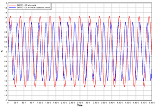
    The last consideration when setting the IDRIVE setting is the target impact. When the metal target interacts with the sensor, it causes the amplitude to decrease slightly while also increasing the sensor frequency. Due to this, it is important to check the sensor amplitude at the closest metal target distance for the application as well as the farthest distance. This is to check that the sensor amplitude does not drop below 1.2V when the target is close and does not go above 1.8V when the target is at its farthest (or not present). If in setting the IDRIVE, both conditions cannot be met, it is more important to be below 1.8V at the farthest target distance.


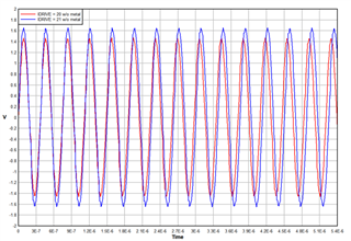
    Below are some examples using the LDC1614EVM and the LDCCOILEVM coil L with a 68pF capacitor. The IDRIVE register was set to 20 for the baseline measurement and the impacts of a metal target and changing the IDRIVE value are shown. The amplitude and frequency of each scenario is summarized in a table at the end.

    Metal Interaction:

    Changing IDRIVE:

    Measurement

    Amplitude

    (V)

    Frequency

    (MHz)

    IDRIVE = 20 w/o metal

    1.4152

    2.693

    IDRIVE = 20 w/ metal

    1.1913

    3.428

    IDRIVE = 21 w/o metal

    1.6085

    2.663

    Best Regards, 

    Justin Beigel