This thread has been locked.

If you have a related question, please click the "Ask a related question" button in the top right corner. The newly created question will be automatically linked to this question.

AWR1843BOOST: Primary bootloader use

Part Number: AWR1843BOOST
Other Parts Discussed in Thread: AWR1843, UNIFLASH

Hello everyone,

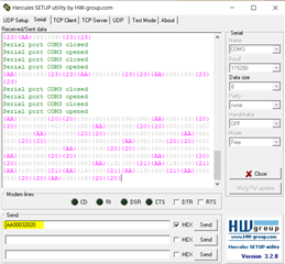
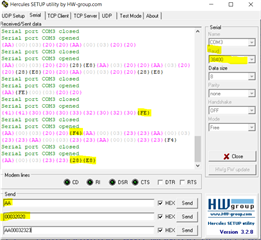
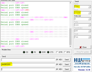
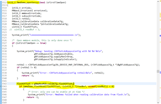
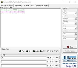
I am trying to test the primary bootloader for my AWR1843 board so I put the radar in SOP mode 5 then I tried to send a ping command through the "Hercules" interface as shown below : 

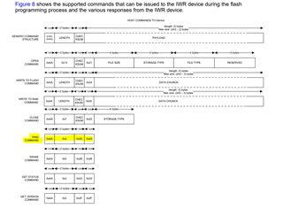
I used this document for support : IWR6843 Bootloader Flow

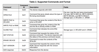
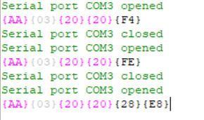
am I not supposed to receive ACK response from the radar 0xCC  as shown in the table because as you can see in the interface I received nothing upon sending the ping command, is there any help with this? Thanks

  • Hi,

    Please give me some time to review this question

    Will get back to you early next week

    thank you
    Cesar

  • Okay Cesar, thanks 

  • Hi Cesar, I tried to send this command with hercules 

    which is the ping command I found in your documents here : 

    but I received no response as well ... 

    One more thing to add, Cesar, is that when I changed various values of Baudrate ( less then 56000 ). I kept getting different responses as the figure below shows 

  • Hello @Cesar Arre there any updates please ? 

  • Hi,

    Sorry for the delay.

    Yes, the information for ping command should be correct.

    First you need to make sure that your setup sends the command correctly. Do you have some logic analyzer you could use to confirm that?

    I checked the errata and there is no known issue related to this.

    No customer has reported this type of issue so far.

    SO, right now I think it is an issue with the setup.

    Thank you

    Cesar

  • Hello Cesar, thanks for answering, 

    one thing that's bothering me is that the radar is returning different responses with different baud rates for the same ping command I am using that's why I am assuming that I am sending the command right because the radar is returning values it's not like it's not responding at all. 

    for example here as you can see I got {F4}, {FE} and {28}{E8} for baud rates 14400, 4800 and 38400 respectively. I got {A9} for example for the 19200 baud rate though I get no response at all for the specified baud rate of 115200 

  • Hi,

    Sorry for late reply.

    I have discussed this issue with the bootloader team.

    First, the bootloader only supports the baud rate 115200. One should not use other baud rates because the response is not relevant.

    Second, before sending the ping command it is required to send a break signal.

    Here is the sequence that must be implemented

    1) Set BREAK

    2) Wait for ACK

    3) Send PING command

    Thank you

    Cesar

  • Hello Cesar, thanks for your answer,

    first of all, this is what I tried to do before you answered me: I used a logic analyzer like you told me and I captured the signal going into and out from the bootloader when I load an image using the Uniflash tool this is what I get : 

    As you can see I get both signals from RX and TX where this is the get version command and then there is the ACK response along with other commands and responses in the analyzer. I sent the same command using my Hercules interface ( the get version command ) but I get no response whatsoever from the device ( no signal shown at channel 1 of the analyzer) : 

    As you can see the command I send with Hercules is identical to the one sent from the Uniflash tool yet I get no response. 

    Of course, I sent the ping command as well ( and I checked it with the analyzer) but I get no response as well.

    Any Idea why that is? and another question since you told me that I should send a break signal first how can I send it ? I mean how does this break signal becomes in binary is it all zeros then I send my ping or something else ? 

    PS : one last thing I tried earlier to send the ping command and get version command too but with 9600 baud rate ( I know that the bootloader should work with 115200 baudrate value) and as you can see in the screenshot below this is what I got in the analyzer ( the command is shown in the channel 2 yellow signal and the response from the device is the blue signal in channel one the ACK response is there ! ) 

    thanks.

  • Hi,

    The UART "break" occurs when the transmitter is holding the data line at logical 0 for a for a minimum of 11 bit times.

    You can send 0xff

    thank you

    Cesar

  • Hi thank you Cesar for the clarification, it turned out that I was missing the break signal indeed in the command I was sending when I added that I got correct responses from the radar, thanks,

    I wanted to ask for example if I want to write some bits into the radar flash I shall use the write to flash command isn't that correct ? and if I do so I didn't quiet understand the checksum byte what should I write in it ? for example if I send this : 0xAA, 0x00, 0x05, 0xFF, 0x15, 0x25, 0x15, 0x17, 0x15

    with the intention to send 5 bytes ( size  is 0x00, 0x05 because it's said that it should be written in 2 bytes) and the 5 bytes I am writing to flash are 0x15, 0x25, 0x15, 0x17, 0x15 then what should I write in the checksum byte ? here in this example I wrote 0xff but I am not sure if that's correct 

    Thanks  

  • Hello Cesar, I used the write to flash command and I got an ACK response from the radar as I wrote 4 bytes into the flash of the radar, any idea how to check the content of the flash memory to check if those bytes were written correctly ? 

    thanks, 

  • You would have to use the QSPI driver to read the content of the flash.

    The CCS debugger does not have capability to read the flash

    thank you
    Cesar

  • Hello Cesar, thanks for your answer I will be getting to that soon and get back to you,

    however, I have yet another question, if I change the flash memory of our device ( MX25 v16) will the bootloader still be working or not ? thanks

  • There is an app note that mentions the flash devices supported by the bootloader

    https://www.ti.com/lit/an/sprach9c/sprach9c.pdf

    Thank you

    Cesar

  • Hello Cesar,

    I designed a PCB with the following flash memory reference : MX25V1635FZUI

    In the note you sent me,  I found one almost similar to it which is the MX25V1635FZNQ so I want to make sure whether the flash memory I put MX25V1635FZUI is supported by the bootloader? thanks 

  • Can you please start a new thread with this question? It would have to be supported by a different team

    thank you
    Cesar

  • Okay Cesar, thanks 

  • Thank you

    Cesar

  • Hello Cesar,

    for the last couple of days I've been trying to use the QSPI driver to read the content of the flash ( of the bytes I sent into the bootloader ) si I added the flash read function at the beginning of the MmwDemo_opensensor API in the MSS main like this : 

    I put a breakpoint there to be able to read the readBuf buffer which is the flash buffer but I keep getting an empty buffer 

    PS : the EVM is in the functional mode of course when I am debugging 

    any idea? 

  • Hi,

    Could you please start a new thread for this topic?

    Thank you

    Cesar