Because of the holidays, TI E2E™ design support forum responses will be delayed from Dec. 25 through Jan. 2. Thank you for your patience.

This thread has been locked.

If you have a related question, please click the "Ask a related question" button in the top right corner. The newly created question will be automatically linked to this question.

PGA460: Dump, Deadtime, Gain setting and DECPL example

Part Number: PGA460

Hello PGA460 team,  my Customer is preparing reference design by PGA460 with direct mode setting.

Would you please kindly let me know following questions?

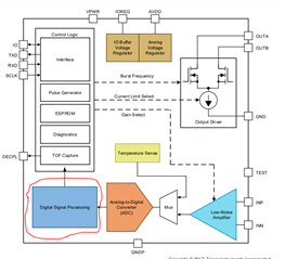
Q1) which point of datasource coming if customer use dump function by Page#48, Fig-35 DSP block diagram?

Q2) P14 deadtime adjustment, Do you know your suggested DEAD Time setting when customer use directmode function?
        also please kindly share how to make decision DEADtime setting parameter ?

Q3) Datasheet Fig69 shows SR/LR Gain curve difference. Could you please let me know why this kind of curve setting of Fig-69?
Q4) using direct connecting by Fig-141 and my customer is considering to apply DECPL.   Do you have example schematic or reference schematic in your side?

Best Regards,

Hironori Yoshimura

  • Hello Hironori-san,

    Thanks for posting to the sensing forum!

    1) Figure 35 indicates how the DP_MUX can be used to extract the digital data from the data dump function at different points. This gives you the option to choose the source to obtain the data dump without having to go through all the block of the DSP path. So it gives you the option to obtain the data from  ADC output, LPF output, rectifier output, or the BPF output. The data still passes through the remaining blocks after the Test Mux block. Keep in mind this function is only available when using USART, since this data is transmitted through the TXD pin.

    The dump data source  basically selected in this DSP block on the device.

    2) The DEATIME setting is used if the device will be used with an external PMOS FET to drive the transducers using direct drive. The DEADTIME adds an additional delay between driving the internal low side and external high side FET in order to avoid having both FETs turn on at the same time and damaging the device due to the shoot-through. I typically suggest using a setting of 0x1100, which is a sufficient for most instances generates dead time of 750ns, the time can be reduced but this mainly depends on the external mosfet the customer chooses, some mosfet gates can be slower to discharge and completely turn the FET off these typically require a higher DEADTIME setting.

    3) Figure 69 is just a register map, were you referring to the digital gain example curves for figure 9?

    4) The DECPL function is only used for transformer based implementations, this is used to decouple the transducer from the transformer. The purpose of this function is two fold to remove the load caused by the transformer on the transducer during the echo listening period and also to compensate any mismatch the transformer may have due to temperature drift on the driving circuitry. This same principle does not apply to direct driven circuitry and will not have any effect on such a circuit.

    Best,

    Isaac