This thread has been locked.

If you have a related question, please click the "Ask a related question" button in the top right corner. The newly created question will be automatically linked to this question.

IWR6843: Interfacing IWR6843 through UART to send Config data

Part Number: IWR6843

Hi,

I have interfaced IWR6843EVM with an Electric IMP controller through UART.

At present, I am able to send the config data using PC to the visualizer and able to read the output data at the electric IMPs end via UART.

I want to send the config data via UART from IMP instead of PC.

Please help me in finding any docs related to this or any format for the config file to send to the IWR

Thanks and regards,
samidha

  • Hi Samidha,

    The configuration of the radar device is done using a CLI (Command Line Interface) over the UART connection. If you take a look at our config files, you will see that they are a basic text file in the format of command param1 param2.... The majority of these commands are well documented in the mmWave SDK User's Guide in the section Configuration File Format. Some of our labs have their own CLI commands that they have added in order to support custom features, and those would be documented in the User Guide for the specific lab you are running. So in order to configure the radar yourself over UART, you will just need to prepare these commands as strings from your MCU and send them one at a time. The radar CLI driver will respond after each command, so you can check for that in order to verify that your command was received and accepted properly.

    Best Regards,
    Alec

  • Hi Alec,

    I have a couple of questions

    1. Do we need any start-stop bits to be added while sending the command?

    2. What acknowledgment is expected from EVM when the command is sent?

    3. "sensorStop" is the first command to be sent and "sensorStart" is the last?

  • Hi,

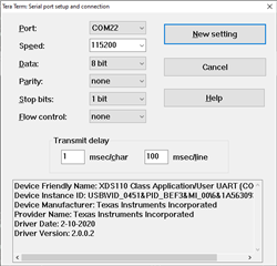
    1. I've screencapped the TeraTerm settings that I use for the CLI port below

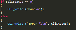
    2. Typically, the CLI driver will echo what you are typing (so that it can be human-readable in a terminal) and once you have sent the command (must end with \n) it should reply with "Done" once the command is successfully executed, or will respond with an errorcode. I will share a screenshot below of the relevant piece of code from the CLI Driver.

    3. Not necessarily. We do this in our included files so that if you send multiple configs back-to-back, it will stop the device, flush the old config, enter the new configuration, and start the device. You may be able to skip some of those steps depending on your usecase if you desire.


    One piece of advice that I may offer, if you are looking to make a custom tool to interface with our CLI interface, it may be best to just manually connect via a Serial Terminal and send a few config files by hand and capture the logs so that you have a reference to compare against when creating your tool.

    Best Regards,
    Alec

  • Hi Alec,

    Thanks for all the info it helped a lot.

    I am able to send the config chirp and get the desired acknowledgment for all the commands except the last one "sensorStart".
    Instead of "Done" or "Debug: Init Calibration status = ox7fe",  I am getting Error -1 message

    Please help me solve this

    Thanks and Regards,
    Samidha

  • Hi,

    Can you share the cfg file that you have sent? It likely is either missing a mandatory command, or has a chirp configuration that is not valid. You could also debug this using CCS to get more detailed error info.

    Best Regards,
    Alec

  • Hi Alec,

    sensorStop
    flushCfg
    dfeDataOutputMode 1
    channelCfg 15 7 0
    adcCfg 2 1
    adcbufCfg -1 0 1 1 1
    lowPower 0 0

    profileCfg 0 60.75 30.00 25.00 59.10 657930 0 54.71 1   96 2950.00 2 1 36
    chirpCfg 0 0 0 0 0 0 0 1
    chirpCfg 1 1 0 0 0 0 0 2
    chirpCfg 2 2 0 0 0 0 0 4
    frameCfg 0 2  96  0 55.00 1 0
    dynamicRACfarCfg -1 4 4 2 2 8 12 4 8 5.00 8.00 0.40 1 1
    staticRACfarCfg -1 6 2 2 2 8 8 6 4 8.00 15.00 0.30 0 0
    dynamicRangeAngleCfg -1 0.75 0.0010 1 0
    dynamic2DAngleCfg -1 1.5 0.0300 1 0 1 0.30 0.85 8.00
    staticRangeAngleCfg -1 0 8 8
    antGeometry0 0 -1 -2 -3 -2 -3 -4 -5 -4 -5 -6 -7
    antGeometry1 -1 -1 -1 -1 0 0 0 0 -1 -1 -1 -1
    antPhaseRot 1 1 1 1 1 1 1 1 1 1 1 1
    fovCfg -1 70.0 20.0
    compRangeBiasAndRxChanPhase 0 1 0 1 0 1 0 1 0 1 0 1 0 1 0 1 0 1 0 1 0 1 0 1 0

    staticBoundaryBox -3 3 0.5 7.5 0 3
    boundaryBox -4 4 0 8 0 3
    sensorPosition 2 0 15
    gatingParam 3 2 2 2 4
    stateParam 3 3 12 500 5 600
    allocationParam 40 100 0.1 20 0.5 20
    maxAcceleration 0.1 0.1 0.1
    trackingCfg 1 2 800 30 46 96 55
    presenceBoundaryBox -3 3 0.5 7.5 0 3
    sensorStart
     
    This is the chirp config I have used. (C:\ti\mmwave_industrial_toolbox_4_10_1\labs\People_Counting\visualizer\chirp_configs\3D_People_Counting)
    I have already rechecked for any human error by comparing this with my code.

    This is working fine when I upload it via visualizer but when I send the command via UART all commands acknowledge with "Done" except"sensorStart" gives "Error -1"
    Thanks and Regards,

    Samidha
  • Samidha,

    I also just copied your configuration and tested it on my device locally, and saw no issues when using teraterm. Did you ensure to reset the device before sending the config? The 3D People Counting does not support reconfiguration, so if you send a cfg after the device has already been configured, it would likely get an error.

    Best Regards,
    Alec

  • Hey Alec,

    Yes, I got it after resetting the device.
    It seems the IWR does not take the command in the middle of runtime.
    We have to reset it and then send the config.

    Thanks, it works!!

    Regards,


    Samidha