Other Parts Discussed in Thread: TMAG5273
Robotic mechanisms require a programmed response to setup and control behavior to accomplish a specific task. These tasks vary from mobile transport to stability controls or manufacturing and assembly jobs. The motion of the robot in every case is controlled through a motorized mechanism which may be driven directly or coupled to the system by some other means such as a gear box, belt, screw, or rack and pinion.
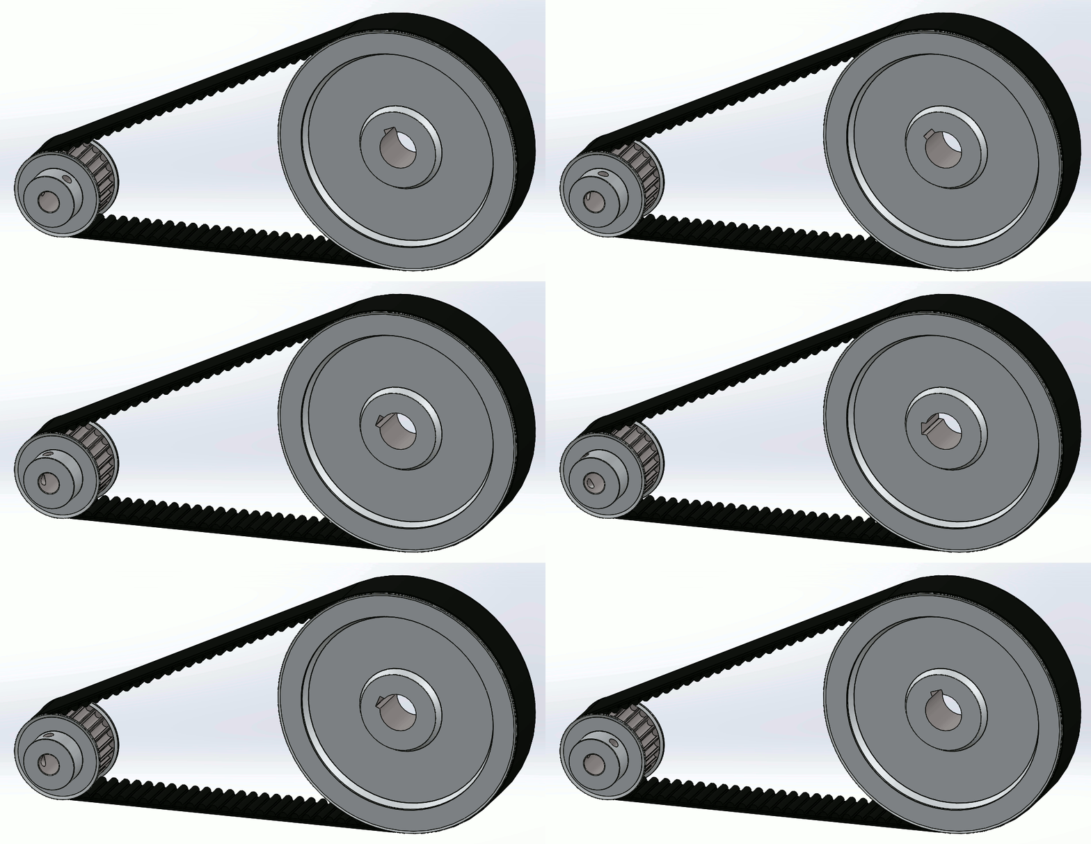
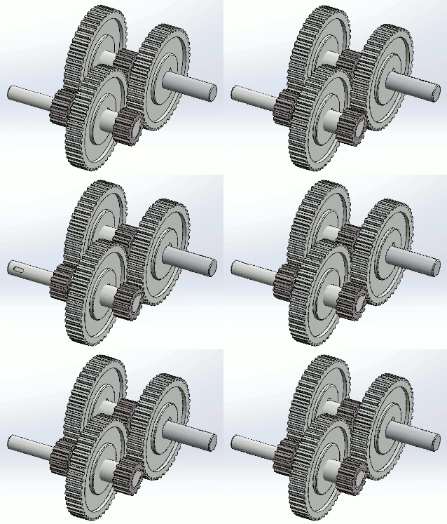

In all cases, the spinning of the motor shaft is coupled to the system. In any application, understanding how the motor shaft position relates to the overall system behavior is critical for a number of reasons.
- Reliable position control for consistent system control
- Reduced risk of damage or injury to the system, nearby objects, and people
- Improved synchronization and sequencing of functions for faster response
These factors impact how well an autonomous mobile robot may guide itself about a warehouse floor or the accuracy and repeatability of a six-axis robotic arm performing assembly tasks. While position information may be derived incrementally from sensors used to commutate the motor, a higher degree of precision is often necessary to produce consistent behavior. Angle encoding is commonly used to track the position of the motor shaft to provide the required precision.
Angle Encoding Solutions
To measure the absolute angle of the motor shaft, an encoder must perform measurements on the shaft itself. Most robotics applications require absolute position information which is commonly obtained using magnetic sensing or optical encoding. To perform reliably, optical encoders require bulky enclosures to protect the sensor from dirt, dust, or other contaminants. Additionally, these solutions must be mechanically coupled to the motor shaft and can become limited in operating speed. Magnetic and inductive sensing are both able to work around both of these challenges. With a magnet attached to the motor shaft, the angular position can be determined by measuring the magnetic field. More information on this measurement is found in the Absolute Angle Measurements for Rotational Motion Using Hall-Effect Sensors application brief.
Magnetic Sensing
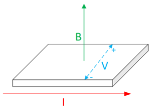
Standard Hall-effect magnetic sensors are one dimensional by nature. The Hall-effect measures a voltage differential in a current-carrying element caused by the Lorentz force. By nature, the applied field, the current, and the voltage is mutually orthogonal. As a result only one component of the three-dimensional magnetic field may be measured by a single device.
To effectively measure angle for a full 360 degree rotation with the arctangent function, two sensing elements separated by 90 degrees are required. The resulting arrangement using standard onedimensional sensors is shown below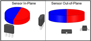
While this method to sense the position of the magnet does provide the required inputs, it requires physical separation of the two sensors about the rotating magnet. Each sensor must be carefully aligned to the magnet to achieve the highest quality input. Overcoming this challenge often requires careful assembly. Surface mount devices may potentially rotate as they self-align during solder reflow and through-hole components require a jig or spacers during assembly to ensure both consistent height and alignment. Even if ideal alignment is achieved during soldering, applied force to the device may bend the leads and produce a non-ideal alignment. For these reasons, a monolithic 3D Hall-effect sensor, such as TMAG5170 or TMAG5273, are excellent options for robotics position encoders. This type of device is capable of measuring and reporting each of the individual components of the B-field vector shown here:
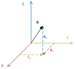
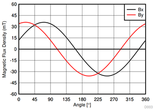
When monitoring each component, the rotating magnet naturally provides inputs to the sensor with a phase difference of 90 degrees.
When using a 3D Hall-effect sensor, the Hall elements used to measure the magnetic field are mutually orthogonal within the same die. As a result, small soldering mis-alignments are more forgiving when finding angular positions because the sensing elements always remain aligned to one another. Sensitivity matching is also improved when using sensors integrated into a single die as they experience similar conditions during manufacturing.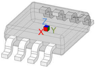
Now with only one package to align, the placement about the magnet is more flexible. Either a ring magnet mounted on the shaft through-hole or end of a standard cylindrical magnet may be used. The sensor is able to be placed conveniently for a compact encoding solution anywhere within range of the magnet that is accessible.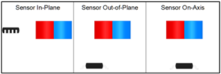
Another great benefit of this family of devices is that they are able to send data back to the microcontroller over a digital interface. Interfering electrical noise is of less concern when transmitting over wire as the digital data is more difficult to corrupt. Cyclic redundancy check (CRC) provides confidence in signal integrity for all read operations. This allows for remote placement of the microcontroller as well, which offers improved versatility in mechanical design. TMAG5170 also is capable of running self diagnostics during normal operation. These include checks for internal memory, VCC status, internal LDO status, output pin voltages, temperature, and other device functionality verifications. This feature provides real-time information regarding the state of the device to help guide system actions that may impact reliability or safety.
For more information and details about Hall-sensors in Robotics, please refer to the content below:
| Name | Description |
| Angle Measurement with Multi-Axis Hall-Effect Sensors | Application note detailing angle measurements using TMAG5170 |
| Multi-mover Position Sensing with Linear Motor Transport Systems | Application brief describing motion feedback in linear motor transport systems |
| Absolute Angle Measurements for Rotational Motion Using Hall-Effect Sensors | Application brief introducing angle measurement using Hall-effect magnetic sensors |
| TIDA-060040 | Reference design and test results demonstrating angular accuracy and calibration in various alignment configurations using both 1D and 3D Hall-effect sensors. |
| TMAG5170UEVM | GUI and attachments incorporate angle measurement using a precise three dimensional linear Hall-effect sensor |
| TMAG5273EVM | GUI and attachments incorporate angle measurement using a three dimensional linear Hall-effect sensor |
| DRV5055EVM | EVM incorporates a digital display with various sensitivities aligned linearly along a ruler face. |
| TI Precision Labs - Magnetic Sensors | A helpful video series describing the Hall effect and how it is used in various applications |

