This thread has been locked.

If you have a related question, please click the "Ask a related question" button in the top right corner. The newly created question will be automatically linked to this question.

LDC1612: LDC1612

Part Number: LDC1612

We are using a LDC1612. We have some problems about this chip.

The inductance we used changes between 1 mH - 1.6 mH, Our parallel capacitance is Cp = 10 nF. 

We configure the registers as follows, respectively:

void LDC1612_Init(void) {

LDC1612_Write(0x1C, 0x0000); // reset all registers
LDC1612_Write(0x1A, 0x1481); // config (Internal clock enable, INTB disable)
LDC1612_Write(0x1B, 0x0209); // mux_config (deglitch filter Bandwidth = 1.1 MHz)
LDC1612_Write(0x08, 0xFFFF); // max conversion time
LDC1612_Write(0x0C, 0x0000); // zero offset
LDC1612_Write(0x10, 0x07D0); // settling time = 0.8 ms
LDC1612_Write(0x14, 0x1001); // clock dividers: 1) fin_div = 1, 2) fref_div = 1.
LDC1612_Write(0x1E, 0xF000); // idrive (we selected this value by controlling it from the osciloscope screen to make sure 1.2 v < Vosc < 1.8 V)

}

1) Our oscillation signal on LC Tank is stopping after start-up. I mean it does not continue oscillating or sometimes, it oscillates for a period of time then it stops. What do you think is the problem?

2) We designed a coil via webench tool. Lcoil = 8.5 uH, Ccoil = 100 pF. We obtained satisfying results. Then we switched the another setup and used the values we stated above (L = 1 mH - 1.6 mH, C = 10 nF). While we are changing the inductance value manually, we expect to see a smooth changing curve related to the inductance change. But, we see a discrete like curve. It feels like some data are missing.  

What are your suggestions about these problems? 

Thanks in advance.

  • Emrehan,

    Have you looked at the equivalent Rp of your sensor inductance and cap?
    The data sheet gives min/max limits of Rp  = 1k/100k.
    Outside these limits, the oscillator might  not work reliably.

    Regards,
    John

  • Emrehan,
    Apologies, but I forgot to mention that we have an app note that gives some information on measuring Rp.
    You can download it from here.

    Regards,
    John

  • Thanks John, we solved our problem related to Rp through the app note you mentioned.

    We have another question about this topic. We have two LC circuit:

    1) C1 = 100 pF, L1 = 8.6 uH, Rp =  2.42 k,

    2) C2 = 1 nF, L2 = 1 mH, Rp = 1.23 k.

    The osc. amplitude for both circuits is between 1.2 V - 1.8 V.  While the range of the LDC1612's digital output for the first circuit is 5 million, and very smooth, the second circuit's output range is 250k and noisy.  

    What do you think about this issue? 

    We are looking forward to hear from you.

  • Emrehan,

    The calculated Q for circuit (1) is 8.25 and for circuit (2) Q is about 1.2.

    While the data sheet doesn't specify min/max values for Q, the value for (2) is a bit low, and most likely the sensor driver can't stabilize to the desired frequency. If this is the case, you can observe this behavior by probing the sensor waveform.

    You can further test this idea by keeping in mind Q = Rp*√(C/L), and by increasing the ratio C/L while keeping the C*L product constant. 
    A good starting point would be to change C/L to make 5 < Q < 10, and increasing Q a little more if the sensor waveform is still unstable.

    Please give that a try and update this thread with your findings.

    Regards,
    John

  • John,

    We increased the Q from 1.82 to 7.2 by placing a 90 uH parallel inductor to our sensor coil (L2 = 1 mH) and replaced the capacitance, now we use 10 nF as C2. With this setup, we observed the measurement range was increased. Also, we realized that the data missing we mentioned in our the first question was due to reading 1 byte from DATA_LSB register instead of 2 byte.

    There are a few other issue we are wondering about Rp and INTB.

    Note: These questions are related to separate systems.

    1) How can we increase the Rp? Datasheet mentions about decreasing the Rp but no information about increasing the Rp.

    2) We want to get the sampling frequency via INTB pin. We configured the registers as follows. But INTB pin was always HIGH. How can we configure the registers for the INTB pin to be high on every LDC conversion? Our final goal is to read the data_registers at every external interrupt (from the INTB Pin), after that filter these data.

    LDC1612_Write(0x08, 0xFFFF); // RCOUNT
    LDC1612_Write(0x0C, 0x0000); // OFFSET
    LDC1612_Write(0x10, 0x0004); // SETTLE_COUNT
    LDC1612_Write(0x14, 0x1001); // CLOCK_DIVIDERS
    LDC1612_Write(0x1A, 0x1400); // CONFIG
    LDC1612_Write(0x1C, 0x0000); // RESET_DEV
    LDC1612_Write(0x1E, 0xC800); // DRIVE_CURRENT
    LDC1612_Write(0x19, 0x0001); // ERROR_CONFIG

    Thank you for your valuable contributions. We appreciate your effort.


  • Hello Emrehan, 

    Adding a fixed series inductor decreases the measurement range because only a portion of the combined inductance is the actual sensor. It can also have a similar impact on accuracy in the system. More information on using a series inductor can be found here: https://e2e.ti.com/blogs_/b/analogwire/posts/inductive-sensing-how-to-use-a-tiny-2mm-pcb-inductor-as-a-sensor

    To increase Rp, you would need to decrease your sensor Rs. You can do this by increasing the trace width or number of turns in the sensor design. Additionally, if you have the space, using a racetrack style coil instead of a circular coil will give you an increases Rp due to the extra trace length in the sensor. 

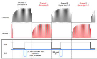
    For INTB, the pin will be high until asserted, so you will be getting a low INTB signal every LDC conversion: 

    The INTB pin assertion gets cleared when the status register is read. 

    In your register writes, it looks like you are resetting the device after you partially configure it. Try moving the RESET_DEV register write to the start of your configuration and retesting to see if the INTB bus is behaving properly. 

    Best Regards, 

    Justin Beigel