This thread has been locked.

If you have a related question, please click the "Ask a related question" button in the top right corner. The newly created question will be automatically linked to this question.

TMAG5273: Sensitivity Question

Part Number: TMAG5273
Other Parts Discussed in Thread: TMAG5111, TMAG5170, , TI-SCB

Hi, We are looking for a replacement for another Hall Effect sensor we have.

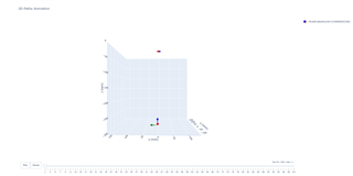
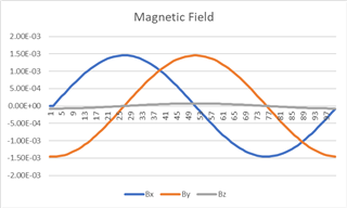
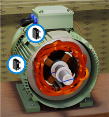
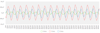
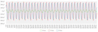
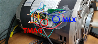
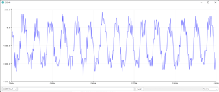
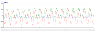
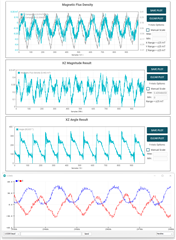
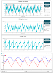
The sensor is on top of a electric motor and we are recording X, Y and Z magnetic fields to calculate RPM and direction. The accuracy is not very important but the sensor must have a good sensitivity.

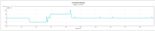
The current sensor is capable of reading changes in magnetic fields 30cm away from the magnet, while the TMAG5273 A2 only change values starting ~10cm away from the sensor.

Am I using the wrong sensor for this application? Is there a way to increase sensitivity and gain?

  • Hello Andrey,

    Thanks for posting to the sensing forum! This is highly dependent on the magnet you are using do you happen to have your magnets specifications? This should help us identify what kind of magnetic fields we should be seeing from your magnet at the 30cm distance.

    The device can definitely be used in this type of application, 30cm sounds really far away but if you have a very strong magnet this can be possible. The device does have built in gain adjustment, typically it is used to further adjust for mechanical misalignments.

    I just have a couple of questions on your end:

    Are you able to observe any magnetic field signal at 30cm away using the TMAG5273 or are you just seeing a flat line with 0mT?

    Do you know what the sensitivity of your previous hall-effect sensor you were using? Was it also a linear hall-effect device?

    If you cannot observe any signal, this means that the field is smaller so it might better to use the A1 version of the sensor since it has a smaller detection range. Looking forward to your response!

    Best,

    Isaac

  • Hi Isaac,

    Thanks for taking the time to look into my post.

    Our previous sensor was a MLX90393 with 5-50mT range with programmable gain, also 3 axis and linear.

    I don't have the specifications for the magnet I am using for testing, it's just a 1.5cm neodymium disc that I have available, we also don't have a single configuration for electric motors so we will have a big range of magnetic fields to work with.

    I thought the A1 in the 40mT configuration would give better results but unfortunately I can't find any, I bought the evaluation kit so I can do more testing using the A1 version as well.

    I did some more testing today and our previous sensor is detecting small changes with the same neodymium magnet at ~40cm.

    I also got a few TMAG5111 B2 Q1 for testing, I like the linear hall effect better because I can get more information but right now I am more concerned about speed and direction.

  • Hello Andrey,

    No worries always glad to help out!

    Okay so I don't have all the magnets specifications, but based on the information given so far this magnet is too far for both of these sensors to be detected appropriately. This magnet would not generate a very strong magnetic field at the distance of ~30cm in order to reliable capture the angle measurement of the magnet.

    You would have to get a significantly stronger magnet or reduce the distance between the magnet and the sensor. Here are the results of a quick simulation based on the parameters I obtained from you.

    The peak field wouldn't even be enough to trigger the lowest sensitivity TMAG5111. The gain on the MLX might help you to be able to detect the signal from that distance but I would be concerned about SNR present. Is 30cm your target distance or are you able to move the magnet closer to your motors magnet. Also you can look into TMAG5170 if you are looking for another 3-axis linear, we have other sensitivity offerings on this device that might fit your needs better.

    Best,

    Isaac

  • Hi Isaac,

    The 30cm is not actually a target, I am just trying to find a sensor that would work in most cases since we have different types and sizes of electric motors. The typical installation would be pretty close to the RMF.

    I got a few more evaluation boards to check the TMAG5170 and TMAG5111. 

    I will continue testing the sensors and hopefully one of them will work.

    Thanks again,

    Andrey

  • Hello Andrey,

    Thanks for the additional info! Thankfully the magnetic field is much larger in magnetic motors so this should give you more margin as to the distance in the sensor placement in comparison to the disk magnet being used in their test. Would you be using this for a BLDC motor commutation?

    Best,

    Isaac

  • Hi Isaac,

    The main application is ACI Motors.

    And you are right about the TMAG5111. Even very close to the motor it was not enough to trigger the sensor.

    Thank you,

    Andrey

  • Hello Andrey,

    Thanks for the info. I am not too familiar with the magnetic field being generated by an AC induction motor, although I imagine it would be similar to a BLDC. You could use TMAG5273EVM and TI-SCB along with the GUI to just view the strength of the magnetic field that is being generated by the permanent magnets. This would give you an idea of what the field around the different places on the rotor looks like and help you identify the ideal areas to place a sensor.

    Best,

    Isaac

  • This is what I did with a small BLDC motor that I wanted to replace the TO-92 sensors on. I measured the field where I wanted to place the surface mount components to see if the field generated at that point was enough to work with the motor I was looking at.

    The red circle is where the previous sensors were located (just on the bottom side of the motor). And below is a picture of what the field looked like when I would measure from the distance I was going to place the sensors: (ignore the spikes this was me manually moving the rotor while still making a measurement)

    So I determined the field was strong enough to change the through hole components to some surface mount ones. With great performance.

    Best,

    Isaac

  • One question I forgot to ask was on the TMAG5111, this has different axis of sensitivity. Did you check which direction the sensor is sensitive in relation to your placement?

    Best,

    Isaac

  • Hi Isaac,

    The AC motors we are using don't have any magnets inside.

    This is the result I get from the current MLX90393. The sensor is outside of the motor. I think the metal enclosure makes it a bit difficult to read the rotating magnetic fields.

    * This is not out target motor, just one we are using for testing.

    *Running at 15Hz.

    For the TMAG5111 I tried the evaluation board, the sensor touching the motor and it was not strong enough to change any register.

    I can do that with the neodymium 3cm from the board.

  • Hey Andrey,

    I thought the rotors of AC motors were also made of magnets is this not the case for all of them? What mechanism do they use to rotate the rotor if they do not use magnets?

    And yes depending on the type of metal the motor housing is made of it could distort your magnetic field hence why you might be getting weird shapes in your field. If the motor does not have magnets what magnetic field are you picking up is this from the coils?

    I apologize for all the questions I am just trying to understand the issue at hand.

    Best,

    Isaac

  • Hi Isaac,

    I am not really an expert in electric motors, I believe there are some new AC motors with permanent magnets but I don't think it's the standard. They need a specific drive to run and we can't just plug them on the wall.

    In the AC induction the stator windings produce the rotating magnetic field which turns the rotor. The rotor is usually a squirrel cage where the bars are shorted, like picture below:

    You are right, the magnetic field that I am picking up is from the coils. 

    This is anexample from another electric motor:

    Usually this signal is not smooth, I am using Savitzky–Golay filter to reduce noise.

    I tried the TMAG5273 A1 today and it's still not enough. My only hope now is the TMAG5170.

    This is my test setup with MLX and TMAG.

    TMAG5273 A1 raw data (only Z axis):

    MLX raw data

  • Hey Andrey,

    Thanks for the info and the quick lesson on how some of the ACI motors work. 

    Based on the two images of the data that you sent over, I believe TMAG5170 should perform more similarly to the MLX device. Reason being is that TMAG5273 transmits the data using an I2C interface and when I look at the data it appears as if its just not sampling as fast as the MLX device, this should be possible with TMAG5170 since it works off of SPI interface and it was better accuracy than TMAG5273.

    As far as the devices performing angle calculations for you outside of the motor as pictured, this might not work as anticipated if you are measuring the field created by the coils. But you could obtain the frequency of the coil excitations and relate that to the motor speed. Direction could possibly be given by another one of the field components but I think there would need to be more testing involved or perhaps a secondary sensor might be needed.

    Best,

    Isaac

  • Hi Isaac,

    I have the TMAG5273 in fast mode.

    Update Rate: 10.0 kSPS

    I2C: 400 KHz

    I believe this should be more than enough for the 1000 samples per second I am looking for.

    I am hoping the better accuracy on the TMAG5170 solves my issue. I should start doing some tests today and give you an update here.

    I am able to approximate the RPM using the motor technical specification and the peaks in the magnetometer, for 60Hz I get 60 top peaks, 15Hz I get 15 top peaks and so on. Direction I can get by comparing Y and Z fields. 

    I just need to improve sensitivity and reduce noise and everything should be fine. I need something a little bit better than the TMAG5273 A1. Or maybe I didn't set up the A1 to get the best signal possible. I will make sure I have all the proper registers there.

    Thanks,

    Andrey

  • Hey Andrey,

    Appreciate the update! Yeah that should be more than enough for the amount of samples per second that you are looking for, but the better accuracy of TMAG5170 should help. Please keep me posted on TMAG5170s performance in this system and glad to hear that you figured out how to calculate the direction using two fields!

    Looking forward to your next update!

    Best,

    Isaac

  • Hi Isaac,

    I was finally able to test the TMAG5170, here's the result compared to MLX (COM3 at the bottom).

    Electric motor running at 10Hz, forward.

    Electric motor running at 10Hz, reverse.

    Looks like with this I can calculate direction a lot easier and the results are similar so don't need to change the way I calculate RPM as well.

    Before we close this, I just have a few other questions for you:

    1. What is the difference between TMAG5170A1 and TMAG5170A1-Q1 (other than the price)?

    2. Since I am reading magnetic fields between +-1mT, do we have any other sensor that can read this kind of weak magnetic fields?

    Thank you,

    Andrey

  • Hello Andrey,

    Glad to hear that all your functions still work as expected.

    1. The difference between the TMAG5170A1 and the TMAG5170A1-Q1 is that the -Q1 version is AEC-Q100 qualified for automotive applications and is functional safety compliant.

    2. For what you are trying to achieve at the moment these are the best two sensors to use.

    I hope this helps and let me know if you have any other questions!

    Best,

    Isaac