Hello,
Section 2.1.1.3 of the Radar Hardware Accelerator User's Guide (swru526b.pdf) implies that a BPM can be applied to a specific chirp and then be decoded by the HWA: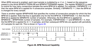
How does one configure phase modulation for a specific chirp?
-- Curtis
This thread has been locked.
If you have a related question, please click the "Ask a related question" button in the top right corner. The newly created question will be automatically linked to this question.
Hello,
Section 2.1.1.3 of the Radar Hardware Accelerator User's Guide (swru526b.pdf) implies that a BPM can be applied to a specific chirp and then be decoded by the HWA:
How does one configure phase modulation for a specific chirp?
-- Curtis
Hi Curtis,
Check out this MIMO Radar Application Report, specifically sections 4.2 & 5, to learn how to configure BPM to a chirp frame.
Regards,
Luke
I am not referring to Hadamard coding of transmit antennas in the time domain as indicated in the linked document,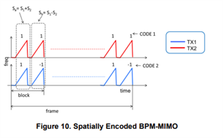
Rather, I am asking about phase shift keying of a chirp with a pseudo-random code: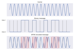
The reference to Hadaman coding in the linked document is actually about applying BPSK to antennas transmitting simultaneously in the spatial domain. It is important to note that the modulation here is happening between chirps, not within them.
For example, if I want to use BPM-MIMO on 4Tx antennas, I will encode the chirps with a 4x4 Hadaman matrix as seen in (b) below:
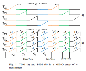
This image is from the Phase-based Doppler Disambiguation in TDM and BPM MIMO FMCW Radars paper, which is also a great resource.
Figure 10 in the linked document is applying BPM-MIMO to the simple 2Tx antenna case, with a 2x2 Hadaman matrix.
Later, we can distinguish the separate Tx signals from one another in the decode stage (referenced in the Radar Hardware Accelerator User's Guide).
So to answer your original question, you must manually define your profileCfg, chirpCfg, and frameCfg in your configuration file such that you implement a BPM scheme. Assuming the 4Tx case, use profileCfg to create a single chirp profile (slope, bandwidth, etc.), then use chirpCfg to define 4 different and sequential chirps of either 0°(+1) or 180°(-1) for each antenna (16 in total). Lastly, use frameCfg to create a subsequence of these chirps. SDK Section 3.4 will help give insight into designing these configuration parameters.
Luke
Again, I think there is a misunderstanding.
I understand how the spatial encoding works and have it implemented in my device FW.
I am interested in applying a phase shift encoding to a transmitter in during the chirp (i.e. phase is changing in the ramp), as opposed to the spatial method which applies a constant phase shift to the chirp.
In the spatial coded scheme you need 2/3/4 subsequent chirps to reconstruct the virtual array, thus there is a significant temporal delay between observations. If a high speed target is in the scene and doppler becomes ambiguous (phase rotates a full revolution between successive chirps), then the phase relationships between the virtual antennas is destroyed. Spatial encoded BMP cannot correct this.
I see references in the HWA user's guide and the mmwave SDK that indicate it is possible to apply a pseudo-random phase modulation to ONE chirp; my question is how to do so?
Edit: As a further point, the paper you reference requires three successive sub frames with differing profiles to estimate the reconstruction.
-- Curtis
Sorry for the misunderstanding Curtis, I follow you now (I am a rookie to the team). I will get someone more knowledgeable on this and get back to you.
Hello.
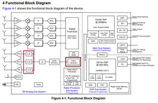
A phase shift encoding during the chirp ramp is not supported in the front end of our IWR6843 sensors.
As you can check from the datasheet of the IWR6843 sensor (Link: https://www.ti.com/lit/ds/symlink/iwr6843.pdf?ts=1654881811435&ref_url=https%253A%252F%252Fwww.ti.com%252Fproduct%252FIWR6843), a linear chirp is generated for each TX antenna.
There are dedicated phase shifters for each TX antenna to support phase encoding (applied to the entire chirp) for typical beamforming or MIMO applications such as BPM. Hence, the BPM removal feature supported in HWA is useful only for such applications.
Regards.
Muhammet
Am I misunderstanding this comment in $(SDK_PATH)\packages\ti\control\mmwavelink\src\rl_sensor.c (SDK 3.5.0.4)?
/** @fn rlReturnVal_t rlSetBpmCommonConfig(rlUInt8_t deviceMap, rlBpmCommonCfg_t* data)
*
*   @brief Sets Binary Phase Modulation Common Configuration
*   @param[in] deviceMap - Bitmap of devices to send the message
*   @param[in] data - Container for BPM common Configuration data
*
*   @return rlReturnVal_t Success - 0, Failure - Error Code
*
*   This API defines static configurations related to BPM (Binary Phase Modulation) feature in
*   each of the TXs. E.g. the source of the BPM pattern (one constant value for each chirp as
*   defined, or intra-chirp pseudo random BPM pattern as found by a programmable
*   LFSR or a programmable sequence inside each chirp), are defined here.
*
*   @note 1: Different source of BPM is currently not supported, hence this API is not required
*            to be called by application.
*/
/* DesignId : MMWL_DesignId_016 */
/* Requirements : AUTORADAR_REQ-724 */
rlReturnVal_t rlSetBpmCommonConfig(rlUInt8_t deviceMap, rlBpmCommonCfg_t* data)
-- Curtis
Hi Curtis,
The comment is misleading. Implementing an "intra-chirp pseudo random BPM pattern" is not currently supported by the front end of our IWR6843 sensors, as Muhammet mentioned.
Regards,
Luke
I see, thank you for the clarification. Any idea if this will be supported in the future?
Regards,
Curtis
Planned development is outside of the scope of this forum; however, if you have any follow up questions, please feel free to open a new thread. Thank you for reaching out on E2E!