This thread has been locked.

If you have a related question, please click the "Ask a related question" button in the top right corner. The newly created question will be automatically linked to this question.

FDC2214: FDC2214 technology support

Part Number: FDC2214
Other Parts Discussed in Thread: , FDC1004, OPA690, FDC2114

Hi,

Our arm mechanical product has a problem for the avoidance function, and we need to make sure Security that the arm medanical sense the near object, for example: the human body or palm and so on; 

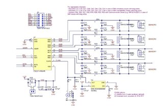
So we choose the FDC2214 to sense the capacitance change to indentify the object distance, and then inform the MCU to move to opposite direction with the object;

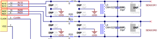
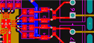
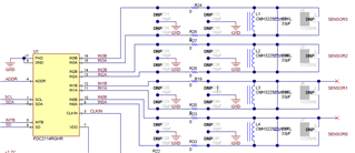
Now our FDC2214 design is similar as the FDC2214EVM as below:

Our arm mechanical is the cylinder and the R=7-8cm, and we stick 4 sensor to interate the 4 direction(Up, Down, Left, Right), each sensor is the rectangle about 5*10cm(Length and width);

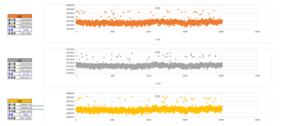
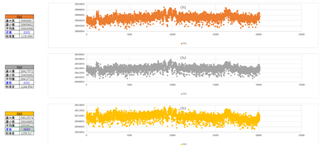
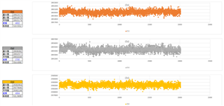
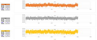
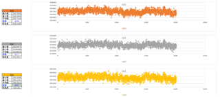
   At first, we stick the sensor above our arm mechanical directly, and there are some noise affect sense accuray which come from the arm mechanical when it is move(the noise is more than 6000ft), we set the

sense accuray larger than 6000ft, the effective sense distance is less than 6cm;

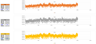
   The sencond, we add the shield layer between the arm mechanical surface and sensor, the space distance between the sensor and shield surface is about 0.5cm, it is shield the noise from the down direction,

the shield layer paramater is Gain=1 and same phase position with the sensor, and we use the amplifier is OPA690IDBVR, now we test the noise intensity, and it is distinct weakening, but the design don't very

well because the noise will come from the around of the sensor because there are 0.5cm space between the shield layer and sensor;

So our issue as below:

1. How to design the shield layer to eliminate the around noise of the sensor;

2. The amplifer is OPA690IDBVR is much more expense, so please promote the better amplifer for this design;

3. Our mimimum testing distance is 15cm, and is there are any more better reference design to solve the noise issue;

  • Zhang,

    One of the challenges with using the FDC2214 is EMI. 
    The capacitive sensors act as receiving antennas for nearby electric fields, and those parts do not have an active shield driver.

    For capacitive sensing designs we advise using the FDC1004 as an alternative to the FDC2214. 
    The FDC1004 is a four-channel capacitive sensor that has built-in active shield drivers. 

    For the FDC2214, there is no mention of the size of the shield layer.
    Is it possible to make the shield larger than the sensor? 
    That may help reduce EMI from below the sensor.

    Unfortunately we don't have any tools yet to help with the sensor design and model the sensitivity.

    What sensor frequency are you using with the FDC2214?

    Why did you pick the OPA690 for your design?

    Regards,
    John

  • Hi John,

    Thanks for your professional comment.

       Now we have tested the FDC2214 in our arm mechanical, we have got some progress for the shield design, so we can't modify the design to FDC1004 

    before we have no solution to increase the accuracy;

       We have used the 3-10MHz sensor frequency for FDC2214 and the signal intensity is  +/-3V;

       The OPA690 is the preliminary amplifier and we will optimize our design, so please advise the better device for the shield drivers, thanks.

  • Zhang,

    I am glad you are seeing progress.
    The signal level does sound a bit high.
    It might be worth reducing the signal level by reducing the DRIVE_CURRENT_CHX so the signal is within the recommended peak voltage of 1.2V to 1.8V.

    A replacement device for the OPA690 should come from our high speed amplifier products that can be found at  https://www.ti.com/amplifier-circuit/op-amps/high-speed/overview.html

    If the shield signal frequency is to be 3-10MHz, then consider other voltage-feedback amplifiers with gain-bandwidth products larger than 5*GAIN*10MHz.
    Just for comparison, the OPA690 has a 500MHz gain-bandwidth product. 
    Please be aware some high-speed amplifiers have problems driving reactive loads, so you may need to have attenuation (resistance) on the amplifier output before the shield signal is applied to the traces and shield. This may force you to pick a higher-voltage amplifier (>5V) that can provide more signal swing on its output pin. 

    Regards,
    John

  • Hi John,

    We has tested the boards and the result as below:

    1. We choose 3 boards to test the noise of the sensor and there are 2 boards noise is more than 7000(Board #1 and Board #2)

        and 1 board noise is below to 4000(Boards #3);

    2. We sampling 20000 data by each board and the detail as below:

    1) We test the #1 board CH1, CH2, CH3 and the result as below:

    #1 noise is more than 9000

    #2 noise more than 8000

    #3 noise is less than 4000

    2)Now we cross-over experiment between #1 and #3 boards, and we swap the #1 and # 3 FDC2214, test the noise of the sensor:

    #1 noise less than 4000

    #3 noise more than 9000

    3) Follow up the above test result , wcross-over experiment between #1 and #2 boards, and we swap the #1 and # 3 FDC2214,

    test the noise of the sensor:

    #2 noise less than 4000

    #1 noise more than 8000

    4) Conclusion:

    We consider the FDC2214 maybe has less consisitency and there are some individual difference;

    5)Support need:

    Plesae advise if we need to calibrate for everyboard, thanks.

  • Zhang,

    Thank you for the detailed results.
    In your tests, were you swapping the capacitive sensors, the FDC, or both?

    What calibration strategy are you considering?


    Regards,
    John

  • Hi John,

    Only swap the FDC, we wants to test the FDC stability for these 3 boards.

  • Zhang,

    It is hard to make a solid recommendation without more information, but based on the information so far, some kind of calibration step may be needed.
    John

  • Hi John,

    OK, thanks for your kindly support.

  • Hi John,

    We have below issue for the reference design FDC2214EVM, compare schematic diagram with PCB laytou,

    the circuit of INA0/ INB0 and INA1/ INB1 are different to connect to sensor, please refer to below:

  • Zhang,

    The component designations on the PCB layout (image from the data sheet) are different from the designations given on the schematic (from the EVM users guide).
    Is that what you are referring to?
    Is there another issue as well?

    Regards,
    John

  • Hi John,

    Yes, as we discussed before, we have no idea to solve the noise issue, and there are more than 20% noise are more than the 4000ft , we need to double check if it is out deisgn and feedback to you soon, thanks.

  • Hi, John,

    Please kindly advise the difference of SCH diagram and PCB laytou in reference design FDC2214EVM, and whici one is right, thanks.

  • Zhang,

    I compared an EVM PCB against the layout and schematic in the FDC2214 EVM Users Guide and it looks like they all agree with one-another.

    Regards,
    John

  • Hi John,

    Compara the EVM sch and PCB layout, the INA1/INB1 and INA0/INB0 are opposite to connect to Sensor, thanks.

  • Hello Zhang, 

    The FDC2114 uses a differential sine wave driver for the sensor. Because of this, the main difference in connecting to IN0A or IN0B is the phase of the sensor driver. This doesn't cause any issues with different sensors being on different inputs because the device only drives one sensor channel at a time. 

    In other words, the choice to have the sensor connected to A or B of an input should not change your sensor measurements. 

    Best Regards, 
    Justin Beigel

  • Hi Justin,

    Reference to the datasheet for the description of CLKIN pin: Master Clock input. Tie this pin to GND if internal oscillator is selected;

    Now, the CLKIN pin is NC, and we have no extend oscillator to connect to CLKIN, we can also get the output data from FDC2114;

    Please kindly advise if why we can NC this CLKIN pin, thanks.

    Schematic diagram as below(We connect to the extend oscillator in below schematic):

  • Zhang,

    The NC on the CLKIN is fine.
    John