


Dear Sirs,
I am using the PGA970EVM with the GUI to study how to interface to a three-wire half-bridge LVDT sensor. The PGA970EVM is currently set up with the default jumpers. The plan is to wire up the PGA970 as suggested in this schematic.
The waveform generator drives a 375mV amplitude 13kHz sine wave on a 0.86V pedestal from P1 to the top pin of the LVDT coil. The waveform generator is in single-ended mode so that P2 drives the 0.86V common mode signal to the bottom pin of the LVDT coil.
For simplicity, let's just consider ADC1 and ignore ADC2 which is connected to the centre tap of the LVDT auto-transformer.
The signal P1 from the top of the LVDT coil is also connected to pin S1P of ADC1. ADC1 is in single-ended mode with VCM enabled. S1N is open circuit. According to the PGA970 datasheet, the S1N pin of the amplifier is pulled up to the ADC1 common mode voltage which has been selected as 0.625V. So, I should just see 0.625V DC on S1N. However, an oscilloscope probe on S1N shows a 150mV sine wave superimposed on the 0.625V common mode. The output of the ADC1 demodulator reads an amplitude of 112mV.
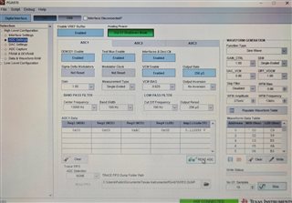
Here is a photograph of the waveform generator and ADC1 settings from the PGA970GUI.
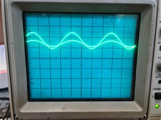
Here is a photograph of the oscilloscope measuring S1P, S1N at 0.1V/div and 20us/div.
My first question is, "Why does the sinusoid appear on S1N?"
I have a secondary question concerning the amplitude measured at the output of the demodulator. I would have thought that this should be 375mV-150mV=225mV since amplifier S1 is differential. However, the PGA970GUI gives the amplitude as 112mV. This is suspiciously close to 225/2, so I wonder if the demodulator output is the peak-to-peak of the amplitude rather than the amplitude itself. By amplitude A, I understand the signal as V(t)=Vcm+A*sin(w*t).
Yours faithfully
Stephen Blake


