This thread has been locked.

If you have a related question, please click the "Ask a related question" button in the top right corner. The newly created question will be automatically linked to this question.

LDC1614: Custom Inductive Sensing Planar coil design

Part Number: LDC1614

Hello everyone,

I have designed a prototype board to work in tandem with the LDC1614, and wanted to ask TI engineers for some advice. TI is always super helpful Slight smile

Here is the goals for the board:

- 0.1 degree resolution (0.5 degree is still acceptable)

- Will be placed in a fully aluminum part, which will have moving aluminum inside as well. The moving aluminum will be around 0.7mm to 1.5cm away from the sensor.

- The board will be a very small package sensing, and will need to detect a target moving in an arc (120 degrees)

- We aim to sense a change in the inductance as target passes over it. We don't care too much about the absolute inductance and LC tank frequency, only the relative change from a calibration point.

Here is the design:

Specs:

- Layers: Either 4 or 6
- Trace Width: 4mils
- Trace Spacing: 4mils
- Board edge to nearest trace spacing: 4mils
- Via outer diameter: 16mils. There is plenty of space in the middle of the board, so we could do 20mils
- Via inner diameter: 10mils. Again, can go bigger.
- PCB thickness: 0.8mm

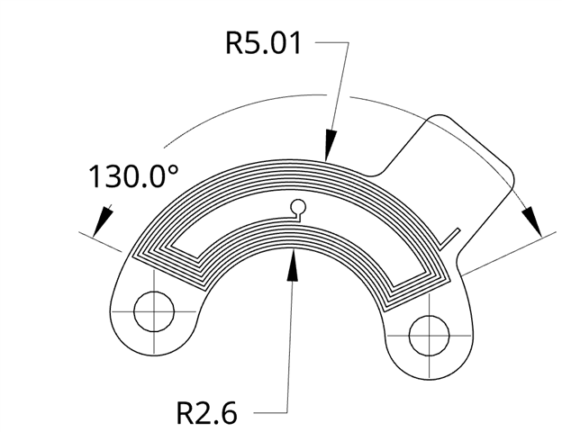
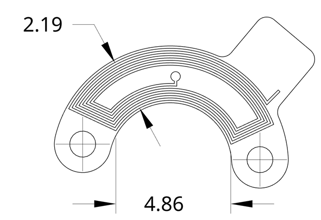
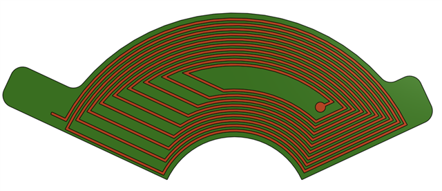
The inductive coil will be put on 6 layers (varying between clockwise rotation, as seen below, and anticlockwise, layer by layer)

Images:


You may have to click on the images to get the resolution needed to see the space between the sensors. The little rectangle on the top left is space for a connector. A 0201 Inductor and Capacitor will be placed on a flex cable that connects to this board. The board is 150 degrees, but we only need to sense 120 degrees of motion. 

The target will be a PCB in the exact form factor as above, except it will just be solid copper.

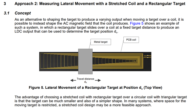
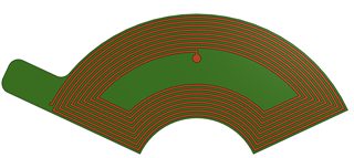
Note that the space in the middle is 31% of the total area, a tip which I got from this paper.

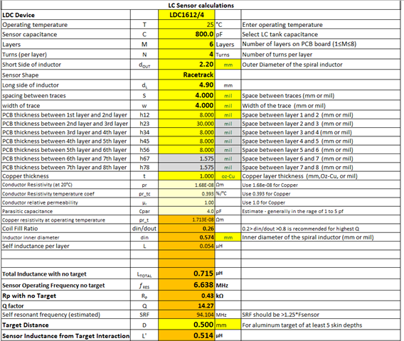
Simulated performance with the LDC1614

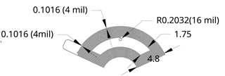
I estimated the coil to be a square. We can imagine if we unbend the traces upwards, the coil will become a rectangle. Approximately, the height of the rectangle will be 4.8mm, and the length will be around 9mm (roughly).

Using TI's WEBENCH Coil Designer, I set the parameter as square coil, 8 turns per layer, 4 layer thickness, 4.8mm outer diameter, 4mil trace width and 4mil trace spacing. Here are the results:


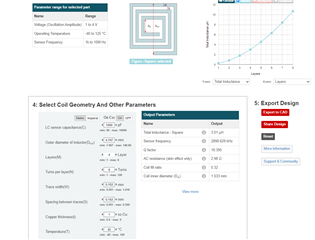
Roughly, the coil is 3.01uH, and with a parallel capacitor of 1000pF the sensor frequency is approximately 3MHz.

Here are some questions I have

- This is the first time I am building something like this. Do you see anything glaringly wrong? Is the 0.5 degree accuracy and resolution min requirement too much?
- The TI paper I referenced above mentions to " Keep the inner 30% of the sensor area unwound for most applications, but for inductive metal button replacement, place as many turns as possible.". It does not mention why? 
- Given that this will operate around moving metal, do we foresee any problems?
- The edge clearance to the nearest trace is 4mils, should we be pushing that farther? 

  • Marko,

    Thank you for your post, and your interest in TI products.

    In your second question, the advice on using as many turns as possible has two considerations.
    The first is that using as many turns as possible maximizes the sensitivity of the sensor and the LDC device.
    Under this constraint, the target needs to be closer to the sensor compared to other applications.
    These factors are okay for buttons, but may not work so well for other position sensing applications.

    The potential sensitivity to surrounding metal will depend on how it competes with your target for influence on the coil.
    Surrounding metal that is the same distance (or closer) to the sensor as your target could reduce the target's influence, reducing resolution.
    If the surrounding metal is much further away, then it might be okay. 
    Any vibration or movement of the nearby metal (and the target) can create variations in your sensor's inductance, which will look like noise on the LDC output.

    A target with the same form factor as the coil will result in ambiguity in the angle estimate.
    In other words, your system will not be able to distinguish if the target is partially covering one end of the sensor or the other. 
    To combat this, your target will need to have a taper from one end to the other. 
    One of our app notes gives some guidance on this. Please see LDC1612/LDC1614 Linear Position Sensing for more information.
    We also have a reference design that might be helpful for your application. 
    Please take a look at the ref design TIDA-00508: 1-Degree Dial Reference Design Using the LDC1314 Inductance-to-Digital Converter.
    It uses complimentary sensors and tapered targets to achieve 0.1° angular resolution.

    An answer to your last question will depend upon the mechanics & tolerances in your system and the material surrounding the sensor. 
    I don't have a definitive answer.

    You might be able to get a closer approximation to your coil by considering a racetrack coil shape.
    You can design a coil with this shape in our Excel-based Inductive Sensing Design Calculator Tool.
    Info on using the tool is available in our Inductive Sensing Blogs, along with a lot of other info on inductive sensing, including How to shield from metal interference and Inductive sensing: target size matters.

     Regards,
    John

  • Hi John,

    Thanks for the advice. The Excel based Inductive Sensing Design Calculator Tool was super helpful!

    I have made a new board and have several concerns. Here is the board itself:


    Once again, I used:

    - 4 mil trace spacing
    - 4 mil Trace Width

    I used the excel calculator, and input all these parameters:


    The sensor inductance is 0.715uH. This seems too low? I have read in some TI papers that ideally you want 1uH to 3uH in the sensor inductor. A series inductor can be added, but do you think that it will be of any use if the actual coil inductance is low. I believe this design is really pushing the limits of the LDC1614 and the concept of inductive sensing. 

    Some targeted questions:

    1) Is the sensor inductance of 0.715uH too low to be able to get any useful results? 
    2) Would a series inductor of perhaps 1uH be helpful to improve resolution? 
    3) At 6.7MHz operating frequency, would you recommend a ground plane between the inductive coils?
    4) Do you think that the "racetrack" model provides an overestimate of this type of coil? I would presume the coil I designed has lower inductance than the excel sheet determines.

    Thanks for the help. We really want our design to work with the LDC1614 (or any other TI LDC), and it would be amazing if we can get something working.

    Kind regards,
    Marko

  • Marko,

    1) The 0.715uH may not be too low in and of itself, but the associated Rp is less than half the recommended minimum of 1kΩ, and less than 2x the absolute minimum (= 250Ω). As a result, the Q is a little low as well. This may keep sensor waveform amplitude on the low side, and thereby reduce the resolution. 
    2) By all means consider a series inductor, but while it increases the overall inductance, it can reduce the Δf of the sensor as your target moves over the range because the added inductor reduces the ΔL . This may not matter for your design, but it is something to keep in mind as you move forward.
    Please take a look at our inductive sensing blog about adding a series inductor to a small sense coil.
    3) I'm not sure I understand all of the points of this question, but in general, a ground plane between the coils would tend to mask the effects of the target, and thereby decrease the resolution. 
    4) The honest answer is I don't know. We don't currently have tools to look at this more rigorously, but they are in development. Hopefully in the next few months we will have a way to do quick checks of coil shapes not covered by our Excel tool. 

    I hope this helps. Please let me know if you have any more questions, and please let me know how the design goes.

    Regards,
    John

  • Awesome John! Thanks for the tips. It seems like we would be willing to try this design, but as you mentioned a low Q factor makes us a bit hesitant. 

    I probably should've mentioned our use case earlier, but we are looking into inductive sensing to do joint angle sensing in humanoid hands. As you can imagine, we need tiny package sizes to fit into the hand. We would need about 24 different sensors for one hand.

    I spoke with our mechanical engineers, and it turns out they can't fit the required target for the above boards. The board size is ok, but if we want to progressively increase the area of overlap with a target, that would be too big. This is because the target would have to be the same size as the inductive coil. At the beginning, there would be no overlap (0 position), and at the end of the motion the target would completely cover the inductive coil (end position). 

    We discussed and saw that perhaps we could try out a stretched coil as referenced here: https://www.ti.com/lit/an/snoa931a/snoa931a.pdf?ts=1656995802831&ref_url=https%253A%252F%252Fwww.google.com%252F


    This would be excellent for us, as we could use a similar board size, but the target would be much smaller. Here's what I've gone with: 


    The left turns are equally spaced by 0.406mm(16mils), and the right side traces are a simple 4mil trace spacing. 

    I would assume as a small rectangular target passes over this, the density of coils that it crosses would be variable across the entire path. This would give us a unique code output from the LDC for every position. I can see that the resolution would vary, with some areas more sensitive than others. 

    Does TI have any tools to simulate strecthed coils?

    Sorry for all the questions, we are really pushing the boundaries here and are still very much in an RnD phase for this approach. Your advice has been extremely helpful in helping us evaluate the best path forward. 

    If possible, would you be open to a quick online call with my team and I about our use cases? We would be able to go into detail about our design, challenges we face and where we want inductive sensing to fit in. You will likely be able to make a better judgement call than us on what the best approach is. 

    Thanks for all the help,
    Marko

  • Marko,

    I am sorry to say we don't have tools to design or simulate stretched coils. 

    Do you have an TI sales engineer or field engineer supporting you or your company?
    They would need to the ones to arrange a call.

    Regards,
    John

  • No we don't have a field engineer supporting us, is there a process for engaging with one?

    Thanks,
    Marko

  • Marko,

    I am not sure of the exact procedure, but it will most likely a while.

    It will be quicker to share a document of your system & use-cases so we can provide feedback. 

    I you aren't comfortable sharing it in the open forum, then we can exchange info via the messaging feature of this forum.

    Please let me know what you want to do.


    Regards,
    John