This thread has been locked.

If you have a related question, please click the "Ask a related question" button in the top right corner. The newly created question will be automatically linked to this question.

AWR2944: SPIA;awr2944;TJA1145

Part Number: AWR2944
Other Parts Discussed in Thread: TMS320F28335

i used AWR2944 to control CAN transceiver(JTA1145),when i read transceiver's id register(addr:0x7d),i can read the correct response by a scope,but,there is always 0 in awr2944 SPI buffer register.

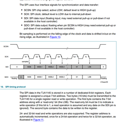
here is transceiver's spi timing protocol:
i have tried use M0、M1、M2、M3 model in awr2944 spi setting.

here is my awr2944 spi config:
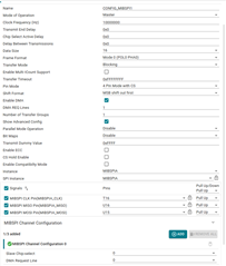
   

in the awr2944TRM file,the awr2944 M0 is "Data is output on the rising edge of SPICLK. Input data is latched on the falling edge.",This doesn't match the transceiver requirements

is it right?

  • I use spi of 28335 board to connect the transceiver of 2944 board and can receive data on 28335 board.

  • Hello Hu,

    If I understood correctly you are trying to wire the SPI lines from the 2944 EVM to another board with JTA1145 CAN PHY? Is that board the 28335  board you are referring to? 

    From 2944 , the SPI modes provided in the TRM are available and the details are captured there. We are not aware of the requirements on the JTA1145 side. You could select the SPI mode that matches the JTA1145 requirements.

    Regards,
    Vivek 

  • thanks Vivek

    the TJA1145 CAN PHY is on my 2944 board,i do not used 2944EVM.

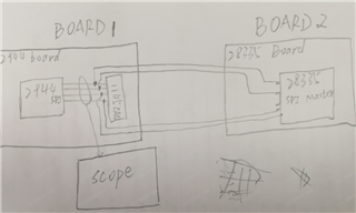
    here is my debug diagram

    the JTA1145 requirements is here

    i think the spi master mode would be sampling data on the rising edge,and transmit data on the falling edge,the SCK pin should be LOW in default.

    i have try M0\M1\M2 mode,and not receive right data

  • Hello Hu,

    I would assume you are using 2944 as SPI master. What exactly is the role of the 28335 board here?

    Regards,

    Vivek

  • hellow Vivek

    28335 board is also SPI Master,

    when i used 2944 board,the 28335 is not connected.

    when i used 28335 board ,2944 board just be powered.

    regards,

    hu zhenguo

  • Hello Zhenguo,

    If I understood you correctly, you are able to communicate to the CAN phy from the 28335 board but unable to communicate to the the CAN phy from 2944 device. Is that correct understanding?

    If that is correct can you probe the SPI lines for one packet length in both the scenarios so that we can compare the timings in both the cases?

    Regards,
    Vivek

  • hellow Vivek,

    1,you are corrrect

    2.here is my sample data

    3. here is my awr2944 programs

    static uint8_t BoardDiag_mcanReadPmicReg1(MIBSPI_Handle handle, uint8_t regOffset)
    {
    uint16_t tx[1];
    uint16_t rx[1] = {0};
    // uint8_t tx[2];
    // uint8_t rx[2];
    MIBSPI_Transaction transaction;

    memset(&transaction, 0, sizeof(transaction));

    /* Configure Data Transfer */
    transaction.count = 2;
    transaction.txBuf = tx;
    transaction.rxBuf = rx;
    transaction.slaveIndex = 0;
    /* Single read transmissions consists of 24bit:
    * Bits 0-7 : Register Address
    * Bits 8-10 : Page address for the register
    * Bit 11 : For Read, value should be 1
    * Bits 12-15: Reserved
    * Bits 16-23: Value Read from the PMIC
    */

    tx[0] = 0xFD00;
    // tx[0] = 0xFD;
    // tx[1] = 0xFD;
    // tx[2] = 0;

    CacheP_wbInv((void *) tx, 2, CacheP_TYPE_ALL);

    /* Start Data Transfer */
    MIBSPI_transfer(handle, &transaction);
    /* Invalidate the receive buffer */
    CacheP_inv((void *) rx, 2, CacheP_TYPE_ALL);

    return rx[0];

    }

    4. This is my TMS320F28335 SPI register setting

    void spi_init(void)
    {
    SpiaRegs.SPICCR.bit.SPISWRESET = 0; //SPI澶嶄綅

    //鏁版嵁鍦ㄦ椂閽熶笂鍗囨部鍙戦�侊紝鍦ㄦ椂閽熶笅闄嶆部鎵�瀛樿緭鍏ョ殑鏁版嵁
    SpiaRegs.SPICCR.bit.CLKPOLARITY = 0; //涓婂崌娌胯Е鍙�
    SpiaRegs.SPICTL.bit.CLK_PHASE = 0; //鏃犲欢鏃舵椂閽�

    SpiaRegs.SPICCR.bit.SPILBK = 0; //鍐呴儴鍥炶矾浣胯兘锛屽疄鐜拌嚜鍙戣嚜鏀�
    SpiaRegs.SPICCR.bit.SPICHAR = 0xF; //鍙戦�佸拰鎺ユ敹鐨勬暟鎹暱搴�16

    SpiaRegs.SPICTL.bit.OVERRUNINTENA = 0; //鍏抽棴婧㈠嚭涓柇
    SpiaRegs.SPICTL.bit.MASTER_SLAVE = 1; //涓绘帶鍒跺櫒妯″紡
    SpiaRegs.SPICTL.bit.TALK = 1; //浣胯兘鍙戦�佸姛鑳�
    SpiaRegs.SPICTL.bit.SPIINTENA = 1; //绂佹SPI涓柇

    SpiaRegs.SPIBRR = 4;//0x1d;//0x63; //娉㈢壒鐜�=150M/4/100=375K //5M

    SpiaRegs.SPIPRI.bit.FREE = 1; //浠跨湡涓嶅奖鍝嶅彂閫佹暟鎹�

    SpiaRegs.SPICCR.bit.SPISWRESET = 1; //SPI鍔熻兘鎭㈠
    }

  • Hello Hu,

    Are both the waveforms from 28335 board? I see that the slave device is responding back with the data in both the waveforms. Can you do a similar capture with 2944?

    Regards,
    vivek

  • the first waveform is captured from AWR2944,and the next is captured from 28335

  • Hello Hu,

    In both the cases I see that the exact same signature is seen on the CLK/MOSI/CS lines (from both 2944 and 28335) and the CAN device is also responding with the same data on the MISO line. So there does not seem to be any issue with the SPI configuration and communication. Are you using the SPI driver code part of the SDK?

    Regards,

    Vivek

  • Hello Vivek,

    yes,i used \mcu_plus_sdk_awr294x_08_02_00_25\examples\drivers\mibspi  demo,just disable loopback ,change mibspi parameter to suit the CAN transceiver.I can send you the project if necessary.

  • Hello Zhenguo,

    We have found the issue on SPIA pins caused due to the conflicting settings on other IO pads. This could be resolved by some internal register write settings. Will get back to you on the exact register writes need to resolve this.

    Regards,
    Vivek

  • Hello Zhenguo,

    Please follow the below configuration for unused pads which are creating a conflict : .

        MSS_IOMUX->PADAD_CFG_REG.IE_OVERRIDE_CTRL = 0x1;

        MSS_IOMUX->PADAE_CFG_REG.IE_OVERRIDE_CTRL = 0x1;

        MSS_IOMUX->PADAF_CFG_REG.IE_OVERRIDE_CTRL = 0x1;

        MSS_IOMUX->PADAG_CFG_REG.IE_OVERRIDE_CTRL = 0x1;

        MSS_IOMUX->PADAD_CFG_REG.IE_OVERRIDE = 0x1;

        MSS_IOMUX->PADAE_CFG_REG.IE_OVERRIDE = 0x1;

        MSS_IOMUX->PADAF_CFG_REG.IE_OVERRIDE = 0x1;

        MSS_IOMUX->PADAG_CFG_REG.IE_OVERRIDE = 0x1;

    Regards,

    Ishita