This thread has been locked.

If you have a related question, please click the "Ask a related question" button in the top right corner. The newly created question will be automatically linked to this question.

FDC2214EVM: Measurement Issue

Part Number: FDC2214EVM

For my calculations, I had taken following considerations. Wanted to know if it was acceptable.


  • CH2 on the EVM, when left open reads ~5.5MHz. That is with the nominal EVM L & “C” values of 18uH and 33pF respectively.
  • Referring to the Electrical Characteristics in the datasheets, it shows that the max sensor capacitance the device can sense is 250 nF based on 1mH Inductor and 10kHz oscillation. However, it doesn’t specify the parallel capacitance used in the LC tank circuit to arrive at those numbers.
  • I used the formula provided in the datasheet and calculated the parallel capacitance “C” to be 3.3 nF.


Base on the above back ground, I chose following values.


                f(sensor) = 5.5MHz (Based on when CH2 when Open, with L=18uH and C=33pF)

                C(sensor) = 23nF (DIY Capacitor)

                C(parallel) = 330pF (picked on random, maybe not since my sensor is 23nF ~10 times lower than what the IC is capable of sensing, I factored the above calculated “C” value of 3.3nF by 10)


Which resulted a L of 36nH.


I wanted to validate the above considerations and results. And if this approach is correct, how else would I need to configure the EVM (in its GUI) to get the appropriate result?

  • Sushant,

    The data sheet provides general guidance on device settings and the EVM user's guide gives some guidance as well.
    Its hard to say more without knowing more about your goals for the end application.

    Regards,
    John

  • John,

    Thank you for the feedback. And apologies for not defining the issue at hand.

    A little background on my issue at hand. I have managed to make a DIY Capacitor (12inchesx12inches) using two copper sheets and polyimide film in-between serving as a dielectric. Using a FLUKE DMM, the capacitance measured is ~23nF.

    I wanted to use FDC2214EVM to measure the capacitance of my DIY sensor and track it over temperature and also be able to record any change in capacitance if some form of mechanical stress is applied on the sensor. 

    Since the EVM already has a Sensor on CH0 and CH1, I chose CH2 for sensing my DIY Capacitor. This is where I am stuck. Upon connecting the DIY capacitor to CH2 (single ended with other terminal of the capacitor floating), The Sensor Capacitance measured by the GUI is wrong. I am aware that there is a chance where I am going to have to change the LC tank circuit (default is L=18uH and C=33pF) on the EVM.

    With that in mind, I took the approach I mentioned above in my post to arrive at those values. I was wanting to know if the approach I took  was correct?   

  • Sushant,

    You mentioned one end of the DIY capacitor is floating. 
    What capacitance reading does the GUI give when the floating end of the DIY cap is grounded?

    Regards,
    John

  • It flags the Channel as saturated and shows that the Input Deglitch Filter (which is initially set to 10MHz) is wrong. Hence, I tried the differential method as highlighted on the datasheet and that didn't help either. In the differential setup, the other terminal of the DIY cap is connected to the second input pin of CH2.

  • Sushant,

    It sounds like something is going wrong with the sensor waveform.
    Can you monitor the sensor signal with a high impedance probe and an oscilloscope for the floating and grounded cases?


    John

  • John,

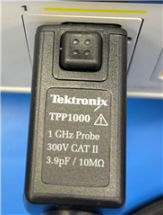
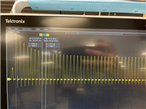
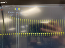
    I have captured the waveform on CH2. Note, that during this measurement, only the scope probe is connected to the one of the input pins of CH2. Please see the attachment. There was not much of a difference between when the GND clip on the probe was connected to the GND reference on the EVM vs when left floating. 

    Images from left to right: probe used, GND clip attached to the GND reference on EVM, GND clip left floating on the probe.

    Thank you,

  • Sushant,

    Thanks for the data. The waveforms look okay.
    Is the setup used for this latest measurement the same that you mentioned earlier in the thread?
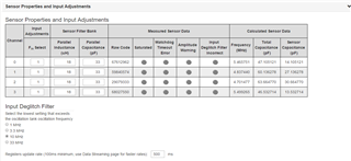
    I', asking because the scope is reporting 4.75Mhz and the GUI reported ~5.5MHz earlier.

    Regards,
    John

  • John,

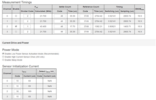
    I have the connected the EVM right now to the GUI, and it this is the report. The only thing i change was the Idrive code for CH2. I saw somewhere in the forum where it recommend to used code 16. Hence I'm using that.  And in the above explanation I had meant to say ~5.0MHz. Apologies for the typo.

  • Sushant,

    I checked with one of my colleagues for a reality-check and he reminded me of an important consideration for these devices. 
    They are not like conventional data converters; the sensor is a tuned circuit - with a finite bandwidth - that provides the FDC device input.

    As you know, the varying sensor capacitance causes a shift in the resonant frequency and this is what the device measures (by design).
    These devices are really intended to measure a change in capacitance, and not a precise value of a fixed capacitance.

    You will most likely need to experiment with different values of the EVM's lumped-element L & C to get the capacitance shift you are looking for.
    These tuned circuits have bandwidths that must be considered, and you can do that with the well-known, simple equations relating R,L,C and Q.
    Otherwise the sensor capacitance range may exceed their input circuit's bandwidth. That may be what is happening now.

    You may have seen it already, but there is some information in one of the later sections (10.2.4) of the  FDC2214 data sheet that may help too.

    Regards,
    John

  • John,

    Thank you for the response. I sort of arrived at the conclusion when I was looking at the datasheet. I knew my configuration had to change a little to exactly measure the 23nF capacitance since having the 23nF in parallel with 33pF, the circuit never sees the 33pF. And my question. 

    Although, as I was going through other posts on the forum where you seems to have help an individual with a similar issue. Although, in that experiment, it was 22nF capacitor that was use. In that discussion, it didnt seem like anything else was change, but the measurement the EVM was giving was around 22nF. 

    I can put in an effort to hunt down the exact post. Please let me know if that is necessary.

    Thanks again

  • Sushant,
    Please feel free to search for the forum for the post you are looking for.
    If you are unable to find what you are looking for, simply post to this thread.

    Regards,
    John

  • John,

    Thank you. I was able to locate the exact post on the forum I was referring to. I am going to "Ask a related question" on the same post and will post my original question in this post. Hopefully we can have a conversation there.

    Thanks again,

    BR,

    Sushant

  • Hello Sushant, 

    I see your other thread and we will continue the conversation there: 

    https://e2e.ti.com/support/sensors-group/sensors/f/sensors-forum/1118784/fdc2214evm-measured-value-not-correct 

    Best Regards, 

    Justin Beigel

  • Hello Justin,

    Thank you for the response. I have posted my comments on there as well.

    Thanks again,

    BR,

    Sushant

  • Hello Sushant, 

    I will close this thread for now as we discuss on the other thread. 

    Best Regards, 

    Justin Beigel