This thread has been locked.

If you have a related question, please click the "Ask a related question" button in the top right corner. The newly created question will be automatically linked to this question.

TMAG5170-Q1: Threshold detection for X,Y, Z ranges

Part Number: TMAG5170-Q1
Other Parts Discussed in Thread: TMAG5170

Hi team,

Q1 . I'm working with Y range set at 50mT value. The value obtained at Y reaches upto 73mT for my product application. Is this correct behavior from sensor ?

Raw Value snippet ,   

mT Value snippet,        

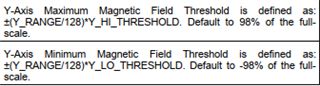
Q2. Secondly I set threshold limits provided in datasheet. I set it to 50% (0x40C0) . My understanding to this is should it be detected at 25mT (Are there any offsets to these threshold detection's )?  As this doesn't happen in application

Q3. On what all parameters is threshold detection decided ?

Regards,

Aditya

  • Hello Aditya,

    Thank you for posting your question to the sensing forum! Firstly, the TMAG5170 has two versions, the TMAG5170A1 and TMAG5170A2, which each have a different set of possible range settings. The device version can be verified on the package itself or in the VER bits on the TEST_CONFIG register (address offset 0x0F) according to the datasheet on pg. 42. If the device is the A2 version (the VER bits are set to 01b), then the range cannot be set to +/-50 mT and your implementation must account for the different set of ranges the A2 version supports.

    For your first question, assuming you are using the TMAG5170A1, the Y_CH_RESULT register value of 0x5AFD you returned should correlate to a mT value of 35.542 mT and not 73 mT if the Y_RANGE bits are set for +/-50 mT. Please double check that your calculation from the result register to the mT value follows the equation provided on pg. 25 of the datasheet. Also verify that the SENSOR_CONFIG register (address offset 0x01) has the Y_RANGE bits set to 00b for a +/-50 mT range on the A1 device.

    For your second question, your threshold register value set for the Y axis looks correct. The mT threshold used in practice will vary according to the range you have set for the measurement. Make sure that the device version and range bits are valid for a +/-50 mT range as outlined above. There is no offset for the threshold values, but there is a changeable offset for the magnetic measurements themselves. Please ensure that the MAG_OFFSET_CONFIG register (address offset 0x12) is set to 0x0000 for no magnetic axis offset to be used. Also please ensure that the Y_HLT_EN bit is enabled on the SYSTEM_CONFIG register (address offset 0x02). If threshold monitoring is being done on the ALERT pin, make sure both the ALERT_MODE bit is set to 1b (for Magnetic Switch mode) and the Y_THRX_ALRT bit is enabled in ALERT_CONFIG (address offset 0x03). In both cases a successful threshold cross will show on the YCH_THX bit in the SYS_STATUS register (address offset 0x0E).

    To summarize for your third question, threshold detection is enabled using the *_HLT_EN bits in the DEVICE_CONFIG (for temperature) and SYSTEM_CONFIG registers (for xyz measurements), set using the *_THRX_CONFIG registers for the associated measurements, and their effective mT threshold values are calculated according to the set *_RANGE for each measurement (except for temperature, which does not have a changeable range). While either of the set thresholds for an axis are crossed, the associated *CH_THX bit in the SYS_STATUS register (address offset 0x0E) will go high and, if the ALERT pin is in Magnetic Switch mode and the *_THRX_ALRT bit for the axis is enabled, the ALERT pin will go low. (the * stands for X, Y, Z, or T -- the associated measurement the bit is set for)

    Please let me know if I misunderstood any of your questions, thanks again,
    Andrew