This thread has been locked.

If you have a related question, please click the "Ask a related question" button in the top right corner. The newly created question will be automatically linked to this question.

MMWCAS-RF-EVM: Device capture order

Part Number: MMWCAS-RF-EVM
Other Parts Discussed in Thread: AWR2243, , MMWCAS-DSP-EVM, TDA2

Hi,

when we capture the data with the device MMWCAS-RF-EVM + MMWCAS-DSP-EVM using the mmWaveStudio tool, some files are generated for each AWR2243 device:
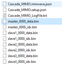
Although the captured data is separated by files (master_0000_data.bin, slave1_0000_data.bin, slave2_0000_data.bin and slave3_0000_data.bin), we would like to know the order in which the data is collected.

Which is the first device that receives the data in the ADC buffer? Is always the same order?

Is it defined in the MMWCAS-RF-EVM  firmware?

Thank you.

  • Hi,

         Every AWR2243 device has separate internal ADC buffer. The RAW data is pushed out from AWR2243 CSI2 interface to TDA2(via VIN to CSI2 bridge(based on lattice FPGA)). RAW data from each AWR2243 is then created in a separate bin file on the TDA2 SSD. The order is Primary device, then subsequent secondary devices. This is not in RF-EVM firmware but is taken care by the studio using the capture application running on the TDA2.

    Regards