This thread has been locked.

If you have a related question, please click the "Ask a related question" button in the top right corner. The newly created question will be automatically linked to this question.

IWR6843AOP: Problem flashing the IWR6843AOP

Part Number: IWR6843AOP
Other Parts Discussed in Thread: , MMWAVEICBOOST, UNIFLASH

Hi,

Thanks for taking time to look into my question.

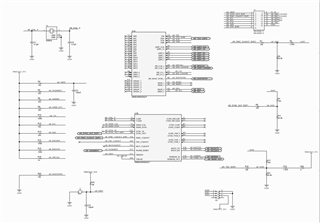
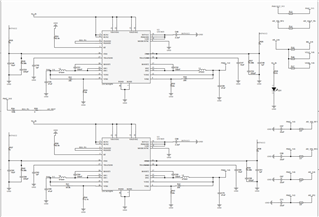
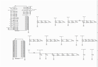
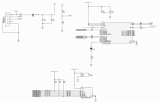
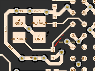
I am using a custom PCB board for IWR6843AOP, most of its design is identical to the IWR6843AOPEVM, including the UART and flash, I directly copy the schematic from the EVM for these 2 parts. But I use another PMIC to replace the LP87524JRNFRQ1.

After fixing some small errors, the board works fine for a week. It can be flashed and output data normally. However, in the last week, sometimes it can not be flashed and eventually cannot be flashed completely today. But, if it is switched to functional mode, it still can output data normally.

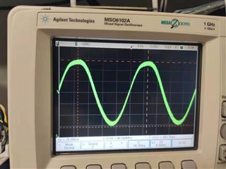
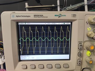
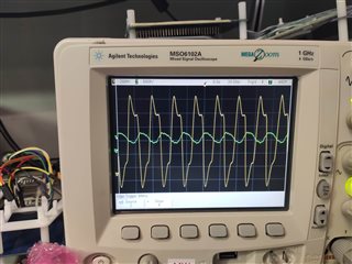
I have tested the UART part by connecting the enhanced COM port with a COM utility in windows. In functional mode, the radar can respond to the commands, thus the UART part should works fine. The radar can output data normally in functional mode, it reflexes the real world results, so the power should not be a problem as well. I do not know how to test the QSPI flash.

I am wondering whether you have any suggestion for me to further debug the board.

Thanks

Piao

  • Hello Piao,

    Thank you for reaching out to TI. 

    Could you provide a copy of your board schematic?

    Also, do you know if anything changed to cause such an issue?

    How are you flashing the device?

    Thanks,

    -Shareef

  • Hi Shareef,

    Thanks for your help!

    1. No problem, the schematic is shown below:

    IO:

    PMIC:

    PWR:

    FLASH:

    I only need the board to communicate with other units through UART and try to reserve the ability to connect to MMWAVEICBOOST for debug. So I only keep the functional part of the IWR6843AOPEVM and rout some signals needed for the debug to a connector. The switches at the breakaway section for SOP0, SOP1 are also keep. All other design should be identical to the IWR6843AOPEVM.

    I use 2 LTC3633 to replace the LP87524JRNFRQ1. Their are set switching at 4MHz, forced PWM mode. The output voltages are within the voltage range specified by the datasheet of the IWR6843AOP.

    There some mistakes in these schematics: (1) I accidentally invert the two data lines of the USB connector in the FLASH schematic, I invert the data lines of a USB cable to correct that. (2) The SOP1 switch in the IO schematic should be connected to a 3.3V according to the IWR6843AOPEVM design. But since the switch remains off in all functional, flash and MMWAVEICBOOST mode, so this should be fine.

    2. As far as I know, there is no change made to the board before it starts to go wrong.

    3. I am flashing the device just like flashing the IWR6843AOPEVM. I disconnect the USB cable, switch the SOP2 switch to on. Connect the USB cable, check the COM port in device manager and open up UniFlash to flash the board. After setting up the path to the bin file and the COM port in the UniFlash, I click the start button. Then, the UniFlash stuck at the opening COM port

  • Hello Piao,

    I have gone through your schematics and dont see anything that might be causing such a problem. I am going to loop in the SW team to assist further and also loop in another team member who might be able to catch something I missed. 

    Thanks,

    -Shareef

  • Hi Shareef,

    thanks for your effort! If the schematic has not evident problem, then it may be hard for you to find out the problem. I think it may relate to my layout or some other details. But it still would be nice if someone can give me some advises.

    Thanks!

    Piao

  • Hi Piao,

    Thanks for your patience! It may relate to your layout or some other details (especially if it stopped working slowly over time) but it could also relate to how you are flashing so I want to check that too! How are you going about flashing?

    Thank you,

    Angie 

  • Also Piao,

    If you have the capability, I need you to probe the XTALP signal to see if you are getting a 40MHz waveform. 

    Thanks,

    -Shareef

  • Hi Shareef,

    this is the crystal part of my board:

    I probe the AR_XTAL_P signal through the pin of the capacitor:

    I just noticed that the crystal was installed rotated 180 degrees compared to the IWR6843AOPEVM. But the waveform on the AR_XTAL_P and AR_XTAL_N seems to be identical to the IWR6843AOPEVM:

    This is the XTALP (green) and XTALN (yellow) of the IWR6843AOPEVM.

    This is the XTALP (green) and XTALN (yellow) of my board.

    Thanks!

  • Piao,

    Can you confirm if the power rails are getting the proper voltage?

    -Shareef

  • Hi Shareef,

    No, the power circuit of this board some times does not work. But the board still cannot be flashed when the power circuit is working properly.

    However, I have a second board that is identical to this board, the second board has been powered on for 5 days continuously and it is still working properly. Maybe this issue is not related to the design but related to the manufacture or something else.

    I think I should first deal with the power circuit and solve its stability issue. 

    Thanks!

    Piao

  • The instability in the power supply could most likely be the culprit here, especially if the second board is the same design and is working fine. 

    Best,

    -Shareef