


Hello TI expert,
Im currently working on occupancy and vital signs lab in automotive toolbox but i cannot understand the config below. Why do we need 2 seperate chirpCfg in this case and what is the different between them? Many thanks in advance.
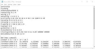
Hello TI expert,
Im currently working on occupancy and vital signs lab in automotive toolbox but i cannot understand the config below. Why do we need 2 seperate chirpCfg in this case and what is the different between them? Many thanks in advance.

