This thread has been locked.

If you have a related question, please click the "Ask a related question" button in the top right corner. The newly created question will be automatically linked to this question.

IWR1443BOOST: Cutting the static and non existing object from point cloud represnetation

Part Number: IWR1443BOOST
Other Parts Discussed in Thread: IWR1443

Hello everybody,

I'm working these days on a project in which i use the IWR1443BOOST, i'm using also the ROS driver developed by the TI team to get the point cloud representation of moving objects in the installation environment, i flashed the oob image for the iwr1443. and i created my own config file bellow :

sensorStop
flushCfg
dfeDataOutputMode 1
channelCfg 15 7 0
adcCfg 2 1
adcbufCfg 0 1 0 1
profileCfg 0 77 118 7 40 0 0 100 1 240 7500 0 0 42
chirpCfg 0 0 0 0 0 0 0 1
chirpCfg 1 1 0 0 0 0 0 4
chirpCfg 2 2 0 0 0 0 0 2
frameCfg 0 2 16 0 33.333 1 0
lowPower 0 0
guiMonitor 1 0 0 0 0 0
cfarCfg 0 2 8 4 3 0 1280
peakGrouping 1 0 0 1 229
multiObjBeamForming 1 0.5
clutterRemoval 0
calibDcRangeSig 0 -5 8 256
compRangeBiasAndRxChanPhase 0.0 1 0 1 0 1 0 1 0 1 0 1 0 1 0 1 0 1 0 1 0 1 0 1 0
measureRangeBiasAndRxChanPhase 0 1.5 0.2
CQRxSatMonitor 0 3 4 99 0
CQSigImgMonitor 0 119 4
analogMonitor 1 1
sensorStart

When i start the ros driver using the appropriate command everything works good like in this RViz representation :


As you can see on the figure the green ellipsoid is a real human moving but the red squares are not real "targets" : the smallest one is just near the radar position or very close to it
the farthest red square from the radar (biggest one) is very near to a glass wall in the detection area
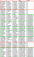
The resulting data was like :(saved in bag and converted to table)

As you can seed the glass wall is the object having the farthest distance on x.
Knowing that i tried to set clutterRemoval to 1 but it removes every point (even the moving targets).
My question is : Is there a way to remove the glass wall representation and the static points just in front of the radar (don't know from where it comes --> there no obstacle near of the radar)

Thank you in advance for your help it will really help me to go forward, and i'll really appreciate.

Abdellah.

  • Hello Abdellah,

    For the red box right next to the sensor, I recommend you increase the minimum distance that points are detected. Those points are the antenna pattern detecting itself due to high sensitivity. Look into the parameter “cfarFovCfg” in the SDK user guide. It will allow you to filter out points impossibly close to the antenna (I would recommend a value of 0.3 for the minimum). For the glass wall, you can try to lower the sensitivity of the sensor via “cfarCfg” and playing with the threshold values

    Best Regards,

    Pedrhom Nafisi

  • Hello Pedrhom,

    Your answer helped me understand more the cfarCfg command, but for the "cfarFovCfg", it look like it was not recognized by the device (rendering : 'cfarFovCfg' is not recognized as a CLI command).

    Please note that i'm using the IWR1443Boost card and the OOB image on it.

    Question : is there any equivalent cli command of "cfarFovCfg" for 1443 device? Or do i have to flash another image on it to make the command recognizable?

    Moreover, when playing on the "cfarCfg" last parameter it eliminates the glass wall noise, but there is no detection at its range of distance.

    Question : is there any parameter helping to maximize the range of detection and eliminate noise.

    Hope you have answers for my questions.

    Thank you for your help,

    Have a good day.

    Abdellah.

  • Hello Abdellah,

    cfarFovCfg not being recognized is due to it being a newer parameter. Unfortunately IWR1443 is over 5 years old at this point and no longer supported, the last SDK version that supports 1443 is 2_0_1 and we are now on 3_0_6 with all other devices. I was not initially aware that the cfarFovCfg parameter was added post 2_0_1 and thus not available on 1443.

    To understand range and noise a little better and how the configuration file you send affects these characteristics, you can play around with the mmWaveSensingEstimator to get a better understanding of what parameters are responsible for maximum range and noise. https://dev.ti.com/gallery/view/1792614/mmWaveSensingEstimator/ver/1.3.0/

    I would recommend using that tool alongside with the SDK User guide that goes over all programmable parameters in detail.

    Best Regards,

    Pedrhom Nafisi

  • Hi Pedrhom,

    Thank you for you answers, i see the problem more clearly now.

    I'm having only one last question :

    Is there any other way to resolve this : " Those points are the antenna pattern detecting itself due to high sensitivity ". is there any other command (then cfarFovCfg) may help me reduce sensitivity?

    Thank you so much for your help.

    Abdellah.

  • Hello Abdellah,

    I would look at a few parameters that could help with your issue:

    • calibDcRangeSig which focuses on Antenna coupling signature removal which is exactly the issue you are having.
    • measureRangeBiasAndRxChanPhase where you can specify a distance where peaks will be searched which can eliminate unwanted nearfield peaks
    • The <guardLen> value within cfarCfg, as well as adjusting the threshold value some more

    Best Regards,

    Pedrhom Nafisi

  • Hi Perdrhom,

    Thank you for your help, i'll also try to tune these parameters and tell you if it will go better.

    Have a good day,

    Abdellah.