This thread has been locked.

If you have a related question, please click the "Ask a related question" button in the top right corner. The newly created question will be automatically linked to this question.

TMAG5273: Wake and sleep mode stops working after a while

Part Number: TMAG5273

Hi there,

I have a low power custom project utilising the TMAG5273 for sensing an open/close function.

The device is configured for Y-axis only, operates in W&S mode and initiates an interrupt on the INT pin when the magnetic field threshold is crossed. The configuration is set to use the absolute field strength so that it will work with both north and south poles. Once the threshold is crossed we read the field value and, once sufficiently high (or low), we swap the threshold detection direction so we can interrupt on the opposite threshold transition. (Note that reading the field value is to provide wider hysteresis for the transition than is provided by just a single threshold value.)

Once the transition takes place we update the I2C registers for the opposite transition and then place it back into W&S mode (the last single I2C transaction). Once in the closed state, the whole device remains asleep and there is no I2C activity.

The issue we have is that the operation usually works, but after some time (minutes to even a day or so) it just stops generating interrupts. The only work-around which seems to "work" is to wake up every minute and send the I2C message to place it in W&S mode, and then it continues to function normally again until it stops again later. This is not ideal for this product and we need to understand how to resolve the issue.

The register configurations are outlined below

Initialisation (only at start-up)

DEVICE_CONFIG_1 = 0x34  // NdBFe temp comp, CONV_AVG = 5 (32x)
DEVICE_CONFIG_2 = 0x22  // THR_HYST = 1, OPERATING_MODE = 2 (continuous)
SENSOR_CONFIG_1 = 0x27  // MAG_CH_EN = 2 (Y), SLEEPTIME = 7 (100mS)
SENSOR_CONFIG_2 = 0x00 or 0x20  // THRX_COUNT = 0 (1x), MAG_THR_DIR = 0 (above) or 1 (below) threshold
Y_THR_CONFIG = 0x02  // Note that the field we are detecting is quite small
INT_CONFIG_1 = 0x44  // THRSLD_INT = 1, INT_STATE = 0 (latch INT), INT_MODE = 1 (nINT)

Then select W&S mode:
DEVICE_CONFIG_2 = 0x23  // THR_HYST = 1, OPERATING_MODE = 3 (W&S mode)

On interrupt event

Read Y value (Y_MSB_RESULT, Y_LSB_RESULT - standard 3-byte read)
If Y > threshold (or less than for opposite transition),
   SENSOR_CONFIG_2 = 0x00 or 0x20 (flip MAG_THR_DIR bit)

Select W&S mode:
DEVICE_CONFIG_2 = 0x23  // THR_HYST = 1, OPERATING_MODE = 3 (W&S mode)

When we reset the W&S mode every minute (work-around), the initial I2C message isn’t acknowledged, but the second one is. This would seem to indicate that it has to come out of W&S mode first, unless it is possible to transit to Sleep (only) mode. As far as I’m aware, the Sleep and W&S modes are the only states where the I2C bus is not active. Is it possible for it to get stuck in sleep mode?

Please let me know if there is something I’m missing in the configuration or operation, or if you are aware of any issues operating the device this way.

Kinds regards,
James.

  • Hi James,

    Thank you for posting to the sensing forum and for all the detailed information. This is not something we have come across yet but are happy to look into it for you. Just a quick question regarding your test setup:

    When you are testing the interrupts in the Wake & Sleep mode, are you generating the interrupts consistently or are you leaving the device alone for some period of time and then trying to generate an interrupt.

    Best,

    ~Alicia 

  • Hi Alicia,

    Thanks for your reply. I responded to the email, but realise I may need to respond here for it to become visible.
    The mode will be the latter. Typically the container it’s attached to will be closed (high magnetic field strength), and occasionally opened for a short while (low but not zero magnetic field strength) before being closed again (high field strength). As far as I can tell the issue only happens when the container is closed (high field strength), but I don’t know if this is relevant.
    I have tried reading the DEVICE_CONFIG_2 register but it always seemed to show a mode of 3 (W&S).
    In the device sleep mode (closed position), there isn’t any I2C activity (measured to be sure). The power is from a coin cell (3V CR2032) and the sensor is properly bypassed. The processor is a nordic nRF52 series device and is sitting in low power mode, other than once per minute it wakes up to update the clock, but this is independent of the sensor or any peripheral device.
    Let me know if there is any other information you need about the setup.
    For comparison, I have also set up the sensor to an Arduino board to run a long-term test independently from our main product which does nothing other than the interrupt handling and field direction reversal for open/close, just in case there is some influence on our main board causing the issue.
    Kind regards,
    James.
  • Hi Alicia,

    I left the test Arduino board (SAMD21) running over the weekend and did have the sensor lock up once. After generating an interrupt manually to trigger the I2C reconfiguration it then continued to work again. This is the same issue we are seeing in our product.

    I have included the test Arduino code below in case this helps. It basically configures the sensor and does nothing until an interrupt is triggered, whereby it changes the interrupt field threshold direction and goes back to W&S mode.

    #include <Wire.h>

    #define BOARD_HALL_I2C_ADDR 0x35
    #define DEVICE_CONFIG_1 0x00
    #define DEVICE_CONFIG_2 0x01
    #define SENSOR_CONFIG_1 0x02
    #define SENSOR_CONFIG_2 0x03
    #define X_THR_CONFIG 0x04
    #define Y_THR_CONFIG 0x05
    #define Z_THR_CONFIG 0x06
    #define T_CONFIG 0x07
    #define INT_CONFIG_1 0x08
    #define DEVICE_ID 0x0D
    #define MANUFACTURER_ID_LSB 0x0E
    #define MANUFACTURER_ID_MSB 0x0F
    #define Y_MSB_RESULT 0x14
    #define Y_LSB_RESULT 0x14
    #define FORCE_CONVERSION 0x80

    #define INTR_PIN  3

    unsigned char g_nDirByte = 0x20;

    void ConfigSensor();
    void I2CWrite(unsigned char nReg, unsigned char nVal);
    void I2CRead(unsigned char nReg, unsigned char* pData, unsigned char nLen);

    void setup()
    {
      pinMode(LED_BUILTIN, OUTPUT);
      pinMode(PIN_LED2, OUTPUT);
      pinMode(3, INPUT_PULLUP);

      Wire.begin();
      Serial.begin(115200);

      Serial.println("Init");
      ConfigSensor();
    }

    void loop()
    {
      // If INT triggered,
      if (digitalRead(INTR_PIN) == LOW)
      {
        Serial.println("INTR");

        // Swap detection direction.
        // Also clears interrupt.
        g_nDirByte ^= 0x20;
        I2CWrite(SENSOR_CONFIG_2, g_nDirByte);
        if (g_nDirByte == 0x20)
        {
          Serial.println("Det low");
          digitalWrite(PIN_LED2, LOW);
        }
        else
        {
          Serial.println("Det high");
          digitalWrite(PIN_LED2, HIGH);
        }

        // Go back to W&S mode.
        I2CWrite(DEVICE_CONFIG_2, 0x23);
      }

      digitalWrite(LED_BUILTIN, digitalRead(3));
      delay(200);
    }

    void ConfigSensor()
    {
      unsigned char aConfig[9] = {0};

      Serial.println("Configuring sensor");

      // Configure hall sensor.
      I2CWrite(DEVICE_CONFIG_2, 0x22); // Wake up
      I2CWrite(DEVICE_CONFIG_2, 0x22); // Continuous mode
      I2CWrite(DEVICE_CONFIG_1, 0x34);
      I2CWrite(SENSOR_CONFIG_1, 0x27);
      I2CWrite(SENSOR_CONFIG_2, g_nDirByte);
      I2CWrite(Y_THR_CONFIG, 0x02);
      I2CWrite(INT_CONFIG_1, 0x44);

      // Read regs to check.
      I2CRead(DEVICE_CONFIG_1, aConfig, sizeof(aConfig));
      for (int i=0; i < sizeof(aConfig); i++)
      {
        Serial.print(i);
        Serial.print(": ");
        Serial.println(aConfig[i], HEX);
      }

      // Enter W&S mode
      I2CWrite(DEVICE_CONFIG_2, 0x23);
    }

    void I2CWrite(unsigned char nReg, unsigned char nVal)
    {
      Wire.beginTransmission(BOARD_HALL_I2C_ADDR);
      Wire.write(nReg);
      Wire.write(nVal);
      Wire.endTransmission();
    }

    void I2CRead(unsigned char nReg, unsigned char* pData, unsigned char nLen)
    {
      int i = 0;

      Wire.beginTransmission(BOARD_HALL_I2C_ADDR);
      Wire.write(nReg);
      Wire.endTransmission(false);
      Wire.requestFrom(BOARD_HALL_I2C_ADDR, nLen, true);
      while (nLen > 0)
      {
        if (Wire.available() > 0)
        {
          pData[i++] = Wire.read();
          nLen--;
        }
      }
    }

  • Hi Alicia,

    I've been able to repeat it a second time, so it will no doubt happen again soon. Let me know if there is anything you would like me to check or measure when it is in this stage.

    Kind regards,
    James.

  • Hi James,

    Thank you for the detailed information. I did not have a chance to look at this today, but I will be able to look at it tomorrow.

    Best,

    ~Alicia 

  • Hi James,

    Would you be able to share a graph/waveform of the current consumption of the device as it oscillates between wake & sleep mode as well as what it looks like when you notice that this error is occurring?

    Best,

    ~Alicia

  • Hi Alicia,

    Sorry for the late response, but since measuring the current waveforms (which inserts a 10R resistor inline with the power rail) I haven't seen it fail.

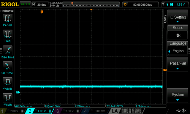
    Interestingly, though, there were times I would short across the measurement terminals in order to switch shunt settings and this would sometimes stop it from working. (Note that the power was never disconnected.) After this the current was about 450 uA which would indicate it is in Standby mode. Given that Standby mode is only entered either from power-up or from a threshold event, could it be that a small change to the power source could cause either of these events. i.e. the operation is sensitive to the power supply rail, causing it to restart or falsely trigger an interrupt?

    The reason I ask is that our product does pulse some indication LEDs which can cause slight dips in the rail voltage due to battery internal resistance, so could also explain why we see the issue. We currently have a 0.1 uF X7R bypass cap right next to the sensor across the power pins and located between the pins and the power rail source.

    As a quick test I'm going to insert a 10R resistor between the power rail and cap to slightly decouple the power to the sensor and see how that works in the product.

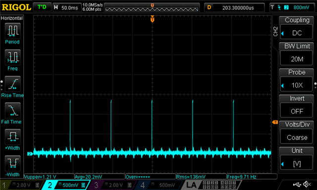
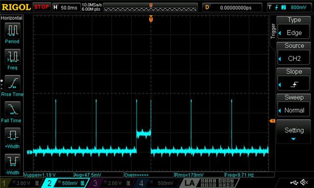
    For reference, I've attached some scope traces of operation (W&S, W&S with INT then clear, and what appears to be standby mode). Note that these were taken using the Arduino-controlled test cct. which is more accessible but which did show the issue earlier.

    Thanks again,
    James.

  • Hi James,

    When the voltage dips, were you able to see what the voltage for it was? Because if it goes below the Vcc minimum (1.7 V), then the device will be sent into stand-by mode.

    Best,

    ~Alicia

  • Hi Alicia,

    We've been running tests for the last couple of weeks. We don't see voltage dips this far but have also added additional power supply bypassing and filtering, much more cotton wool than we have ever applied to other parts. However we still see it occasionally return to standby mode, although it does vary from one device to another.

    At this point we have had to work around another competitor's fixed-threshold device which doesn't experience these issues, which is a pity as the TI part would give us other functionality. However, with 10s of thousands of these expected in the field we can't take any risks.

    We may continue to test these in the background in case we get a breakthrough, but can't afford to commit more time and money into this which has cost us thousands of dollars already!

    If we get any positive results I'll post them here (if the thread is still active).

    I'd like to take this opportunity to post a couple of feature ideas which I believe would greatly improve this device:

    - Interrupt generation when crossing the threshold from either direction, rather than only one direction at a time (with hysteresis of course)

    - Option of going back to W&S mode after triggering an interrupt, rather than staying in a standby state where it no longer performs any detection.

    I would imagine these features would allow it to run continuously without interaction from a processor for quite a number of simple applications.

    Thanks again for your help,

    James.

  • Hi James,

    Thanks for the feedback. I was able to set up a test with your configurations and did not seem to run into any of the issues that you are having, so I am not sure what could be the issue that you are experiencing.

    We would appreciate any comments that you may have should you continue to do some more testing. 

    Best,

    ~Alicia