This thread has been locked.

If you have a related question, please click the "Ask a related question" button in the top right corner. The newly created question will be automatically linked to this question.

IWR6843ISK: How to get RAW IQ data in realtime from IWR6843ISK mmWave Sensor

Part Number: IWR6843ISK
Other Parts Discussed in Thread: MMWAVEICBOOST,

Hi there

I am busy with a group research project that uses multiple different types of sensors to monitor health. All the sensors need to be integrated together with ROS2. I have been put in charge of the radar sensor to get vital signs (breathing and heart rate). I do have access to a DCA1000 (and mmwaveICBoost) board but I can't find any resources on how to work with the board in realtime. Ideally I'd like to be able to output a continuous stream of raw IQ data over serial into a python/c++ program for processing to get the phase and publish into a ROS2 bag. 

I need to:

  1. Configure the waveform parameters.
  2. Read in the data from the radar. 

I know how to configure the waveform in mmwave studio but I can't figure out how to do it without mmwave studio (can you generate a config file with mmwave?). Is this possible to do?

Additionally, I have seen that the iwr6843isk can publish data over uart into python via the serial module. But I can't find what format the data is sent or if its preprocessed or raw IQ data.

I've been struggling for a while with this now. I've tried mmwave studio. I've tried using the ROS1 drivers for the mmwaveICBoost and 6843 board. I've even tried using the DCA1000 CLI to start and stop the sensor via python subprocess module but that didn't work either. Is there a simple way to just read in the raw data?

Best regards

Nic

  • Hello Nic,

    For some context, all of our output formats for Vital Signs via ISK and UART can be found on our Industrial Toolbox for mmWave Sensors under the "Developer's Guide" section. https://dev.ti.com/tirex/explore/node?a=VLyFKFf__4.12.0&node=AKU0Y-htBc6mwPY1fsOUvw__VLyFKFf__4.12.0

    Have you seen this document and is the data output too high level for you? I want to see if you even need a DCA1000 for the project you are working on as it gets significantly more complex if you do.

    Best Regards,

    Pedrhom Nafisi

  • Hi Pedrhom 

    Thank you for your response. I apologise for replying to it so late. I was caught up in some other comittments. 

    Yes unfortunately the data output of the vital signs lab is too high level. The goal of the research is to create a high quality multi modal data set which includes radar data. This means that we need the raw IQ data. As far as I've read the DCA1000 board is requried for raw data capture because only the ethernet port has high enough data rates.

    I've been working a bit more on it for a while and I've been able to communicate with the DCA1000 via ethernet commands to arm DCA1000 for recording using a python script and the socket module. However, we are not getting any data packets out from port 4098. I believe this is because the radar board (mmwaveICBOOST + IWR6843ISK module) is not starting. I am now trying to figure out how to configure the radar waveform and get it to start to send adc samples over lvds to DCA1000 and then monitor ethernet traffic with python to extract the packet data into python. Current approach is to load a config file as generated by the demo visualiser software  over uart to device but this approach does not seem to work. Board has the rf_eval_firmware uploaded to it. It works fine with mwmavestudio but not with my code. Can you give any guidance on:

    1. What hardware coniguration (muxes etc.) the mmwaveICBoost and IWR boards should be in.

    2. Which binaries should be uploaded to the board for control of the board via uart while interfacing it with DCA1000. 

    3. Parsing configuration information (profile parameters, adc parameters etc.) to board over UART serial

    4. Starting and stopping the board over UART serial and getting data to be sent to DCA1000 for capture with python script monitoring ethernet. 

    Alternatively could the DCA1000 SPI interface be used to perform configuration and control of board with custom script. If this is possible/easier could you please advise on how to accomplish this. 

    Best regards

    Nicholas Bowden

  • I guess what we basically want is something that works similary to mmwaveStudio but will ultimately be controlled by a ROS2 node and we have complete control of how, when and where the data is stored and can add any metadata we like such as timestamps etc. The whole system is run off an AGX Orin using ubuntu 20.04 ROS2 foxy fitzroy. Thus mmwaveStudio can't be used because its linux not windows and mmwavestudio isnt suited to the control of other sensors. 

    The flow of code would essentially:

    Configure all devices in the radar system (DCA1000, mmwaveICBoost + IWR) and arm DCA1000 so its ready for capture as an initial setup.

    Then whenever is required by external control loop a set number of frames can be triggered to collect data.

    Rearm DCA1000 so its ready for the next trigger.   

  • Hello,

    So first off let me refer you to some documents 

    DCA1000 Datasheet: https://www.ti.com/lit/ug/spruij4a/spruij4a.pdf?ts=1664297090094

    DCA1000 User Guide: https://dev.ti.com/tirex/explore/node?a=VLyFKFf__4.12.0&node=A__AGTrhNYW8jE6cMxbovlfaA__com.ti.mmwave_industrial_toolbox__VLyFKFf__4.12.0

    Studio-CLI: https://dev.ti.com/tirex/explore/node?a=Z2F8GEn__1.2.1&node=A__AAqrdvmyB0iH1FeHk4CeoA__com.ti.mmwave_platform_toolbox__Z2F8GEn__1.2.1

    mmWave SDK User Guide (Out of Box Demo): https://www.ti.com/tool/MMWAVE-SDK

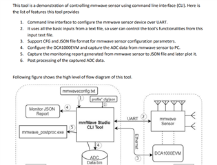
    There are two viable ways you can go about getting raw data from the sensor WITHOUT mmWaveStudio. If you are looking for ONLY raw data, the quickest/easiest solution would be to check out the Studio-CLI link where you can use CLI commands to trigger frame recording and saving of post-proc data. If you need point cloud data on top of the raw data, you can use Out of Box demo and then enable LVDS data transfer which is a larger feat. If you want to go down this route you will also need to check out the DCA1000 source code for CLI commands which can be found in the mmWaveStudio installation at C:\ti\mmwave_studio_02_01_01_00\mmWaveStudio\ReferenceCode\DCA1000\SourceCode.

    Best Regards,

    Pedrhom Nafisi

  • Hi Pedrhom

    Thank you again for your swift response. 

    I've looked at those documents you have suggested and the studio-CLI seems to be potentially exactly what I need based on the block diagram and description is provides.

    However, the document mentions a file structure that I can't find anywhere. 

    I can only find the following within mmwave studio (I also looked at the SDK 3.5 software I have installed) and looking through that code I can only find code pertaining to the DCA1000 (which I already have working in my own script) and not the UART interface to configure and control the radar. 

    Is there a software package I am missing or is the document outdated or am I just looking in the wrong place? If so please advice on where I can find the code I am looking for. 

    Best regards

    Nicholas Bowden

  • Hello Nicholas,

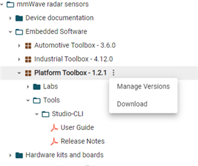
    You will need to download the Platforms Toolbox for mmWave Sensors via clicking the three vertical dots next to it and hitting download. This will give you a zip file and within a folder called tools you will find the Studio-CLI directories you were looking for.

    Best Regards,

    Pedrhom Nafisi