This thread has been locked.

If you have a related question, please click the "Ask a related question" button in the top right corner. The newly created question will be automatically linked to this question.

LDC1614: Inductance value increased with time

Genius 9880 points
Part Number: LDC1614

Hi Team,

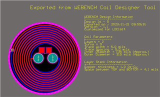
My customer is using LDC1614 Sensor  but they are having a problem with LC coil design. According to them, when they powered up the circuit, the inductance's value increases with time continuously. The value is differing from LC coil to another LC coil and the one LC tank is increasing with time, for example 2533529900 >>>2632987655 

Thank you.

Regards,
May

  • Hello May,

    Thanks for reaching out on the forum.  How is your customer measuring the inductance and is the temperature in their environment relatively stable? 

  • Hi Patrick,

    Please response from customer

    Im using MCU with LDC1614 and LC coil . I used Texas's LC coil it works fine with my code and I also used My coil(normal inductor and normal Capacitor) it works fine for alittle of distance. When I'm using PCB LC coil by Workbench tool it works but it is increasing with time(it works after that its value increased continuously )

    he temperature is room's temperture ...its value 1.day is 25103654839 after that 2.day is 25207654732 >>> 5.day is 26538763964 it reaches to my Threshold value in my code

    Regards,
    May

  • Hello May,

    Thanks for providing that information.  However, I still need some more information to understand your customer's test case.

    1. Does this issue occur for TI's coil as well?  The TI coil your customer tested, is it the one included with the LDC1614EVM or on of the coil kits such as LDCCOILEVM and LDCTOUCHCOMCOILEVM?

    2. When your customer says "PCB LC coil by Workbench tool", do they mean theSensing Solutions EVM GUI Tool v1.10.0 (Rev. F) found on the LDC1614EVM product webpage under Order & start development?  If not, can they provide me a link to where they got the software they are using.  If this refers to their MCU code, then there might be an issue with their code, unless they can duplicate it on our software.

    3.  Over the course of the 5 days, was the coil displaced from its original location?  If it was moved near a metal object over the course of those 5 days, you could see a shift in the measured value.  Also, they should be cognizant of probes or wires near the coil, as the metal could influence the value.

    4.  Can your customer provide some information on what capacitor they are using.  A low ESR capacitor such as a ceramic one is preferred. If your client can provide the part name, that will be helpful in allowing me to look at the datasheet and see if there are any other specifications that might be negatively impacting their test case.

    5. From the first post, it looks as though the capacitor footprint is within the coil center?  Was this generated by the webench coil designer tool, or did your customer make some modifications?  Were those vias also generated by the tool?  From my experience Both the cap and the vias are typically on the outer perimeter of the coil. I think your customer should stick with the recommended design.

    6. Are there any strongly radiating devices nearby?  If significant noise couples to the LC lines that could influence the readings.  Does your customer have EMI filter caps like what is shown in the layout guidelines section of the datasheet?  Could your customer provide us a picture of their coil, cap, traces to LDC1614, and the LDC1614.  This will likely help us with determining any layout issues or non-recommended bench practices for our devices.

    7.  Does your customer have access to an LCR meter?  It would be useful to know if the measured value matches up with what he or she expects.

  • Hi Patrick,

    Just received response from customer, please see details below.

    1 & 2. I used LDC1614EVM board for test this LC Coils(Taxas's LC Coil , My normal inductor capacitor in parallel LC Coil and My PCB LC Coil by Texas LC Coil workbench tool design) I had fine results for one clock time only I didn't test them for long time. I moved to the Code with MicroController I had also fine results for one clock time but When I tested for long time I noticed to Taxas's LC Coil and My normal inductor capacitor in parallel LC Coil worked fine but My PCB LC Coil by Texas LC Coil workbench tool design not. I did firmware upgrade for LDC1614EVM board and it doesn't work now to go back to test them for long time(What is the solution form this problem I connected USB cable to board and did firmware upgrade from LDC1614EVM software tool)

    3. I never didn't move this coils from its place and wires near the coil are constant

    4. I used ceramic capacitors in my project and 1000 PicoF ceramic Capacitor in coil

    5. I have to design LC Coil 8mm diaout for my project and capacitor not fit in out of coil Can I put capacitor out of coil

    My circuit is here ... LDC1614 , ceramic capacitors ,40 MHz crystal and my PCB LC coil. My PCB Coil is here

    Thank you.

    Regards,
    May

  • Hello May,

    Thank you for providing those details.  I dont think putting the capacitor within the coils is recommended.  I will see if my colleagues can provide any further insight on why that might be so tomorrow.

  • Hi Patrick,

    Thank you, looking forward to your update.

    Regards,
    May

  • Hello May,

    Still looking into the layout aspect.  However, in the mean time I think it might be worth suggesting your customer use the coil with our EVM GUI over the course of the weekend.  If the number does not drift on that, it would rule out the possibility of it being related to the hardware and indicate that there could be a software issue.  My postulation, is that there could be something occurring that increments one of his variables over time.

  • Hi Patrick,

    Customer have the EVM however it seems that when he upgraded the firmware the EVM does not work, please see details below.

    I upgraded LDC1614EVM like this document in 2.9 point. I used wrong file for firmware upgrade now EVM does not work. Is there a way also to solved this problem?
    snou135a_USER GUİDE.pdf

    Thank you.

    Regards,
    May

  • Hello May,

    I need to consult one more person for the layout aspect. I should be able to do that Monday.

  • Hello May,

    I spoke with our systems engineer and while placing the capacitor in the coil is not recommended, he did not think it would have a significant impact on the performance in this case. 

    Aside from that, I performed my own test over the weekend with our EVM and GUI and found that while there is some drift, it is nowhere near as large as what your customer has observed.  The difference between my max and min values was a little less than 6000.  This makes me think your customer might have a bug in their software.

  • Hi Patrick,

    Good day! This inquiry was re-opened by the customer. I will continue to assist and I am looking forward to your support. 

    Here is the lates update with the customer. 

    My software code works with your LC Tank (Texas's LC Tank) for long time and no problem I tested my software with two Texas's LC tank it works fine and return with the same value(stable).

    I tested my Hardware and software with texas LC tank it works fine.
    I tested my Hardware and software with my LC tank designed by Texas LC tank designer Tool but every LC tank gives different value and it doesn't work for long time with the same value its value incresead suddenly

    Did your Systems Engineer test Texas software GUI with my LC tank design for long time and track its value?
    Did your Systems Engineer test Texas software GUI with another my LC tank and give same value?

    Thank you in advance!

    Best regads,

    Jonathan

  • Hello Jonathan, 

    We do not have their coil design here to test with but one step we can do to get a better understanding is to look at the sensor oscillation with an oscilloscope. The LDC1614 operates on a discontinuous sine wave driver so it will be best to connect 2 different oscilloscope channels to the IN0A and IN0B connections to the coil. You can go a step further and take a differential measurement of the coil or use the math function to take CH1-CH2 on the oscilloscope to see the full sinusoidal wave. If you could share a screenshot of the waveform it would be helpful for us to ensure the device is working properly with the coil design. 

    When the data values are drifting, is the oscillation consistent or are there changes in the frequency/amplitude? 

    Lastly, what is the target distance for this application? 

    Thank you, 

    Justin Beigel